- 6 -
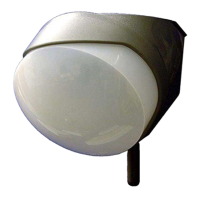
ALIGNMENT OF THE OPAL RFX
Passive infra red movement sensors detect
the temperature changes of moving
objects. Movement across the beams
produces the best response and range
whilst movement towards the detector
would be less responsive. Use the pan and
tilt facility to accurately target the detection
zone, and adjust the range of the detector
to cover the required area.
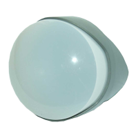
The clear mask supplied with the detector
can be applied vertically or horizontally
to eliminate coverage of a single beam to
an entire long range section. When
mounting higher than boundary fences
mask off any side beams that fall outside
of the required detection area.
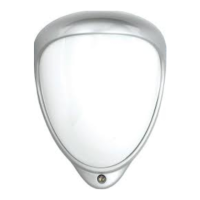
Ensure the detector is mounted upright on
a vertical surface.
CHANGING THE RANDOM CODE
In the unlikely event of another radio
signal affecting the correct operation of a
single channel. The Opal RFX detector
can generate an alternative random code.
Press the program button on the Opal
RFX nine times. On the ninth press 'hold'
the button down for 5 seconds until the
LED goes out, then release the button
.
Erase the code from the receiver by hold-
ing down that channel button until the
beeps stop, then repeat steps '2' to '6' of the
'Setup' procedure to register the new code.
TESTING THE OUTPUTS
(Alignment of the detection beams)
When the 'program' button is pressed
momentarily the red indicator lights and
pulse count '1' is automatically selected.
The unit can then be tested, the red indicator
will light on the Opal RFX and the
respective Channel indicator will flash
every time a detection takes place. This
test mode will automatically cancel five
minutes after last detection. Alternatively,
to cancel 'walk test' press the program
button twice to put into the standard low
power mode.
MOUNTING AND INSTALLATION:
The electronics must be protected against
water during installation as trapped mois-
ture can effect or damage the unit.
1) First remove the front polythene cover
by pulling forwards, then remove the
lens module by pulling it out of the forked
bracket.
2) Drill the wall to accept the fixing
screw supplied with the wall plug.
4) Always ensure when replacing the
module that it is the correct way
up for correct alignment of the beam
pattern.
See page 3 Multibeam lens data.
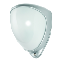
At this stage, weather permitting, the unit
can be tested with the front cover fitted.
Press the program button once to put the
unit into 'walk test' mode. The LED will
light on detection as you walk through the
coverage area. Adjust by using the pan
and tilt the lens module to obtain the
correct alignment and adjust the range
until the correct coverage is obtained.