© Dimplex Boilers 2008
65mm 60mm 60mm 65mm
10mm
Condensate
Drain
CH Flow
(22mm)
Domestic Hot
Water Outlet
(15mm)
Gas Inlet
(22mm)
Mains Cold
Water Inlet
(15mm)
CH Return
(22mm)
Tap Rail
446mm
264mm 182mm
796mm
150mm
94mm
333mm
148mm185mm
1.5° - 3.0°
Tube Ø 100mm
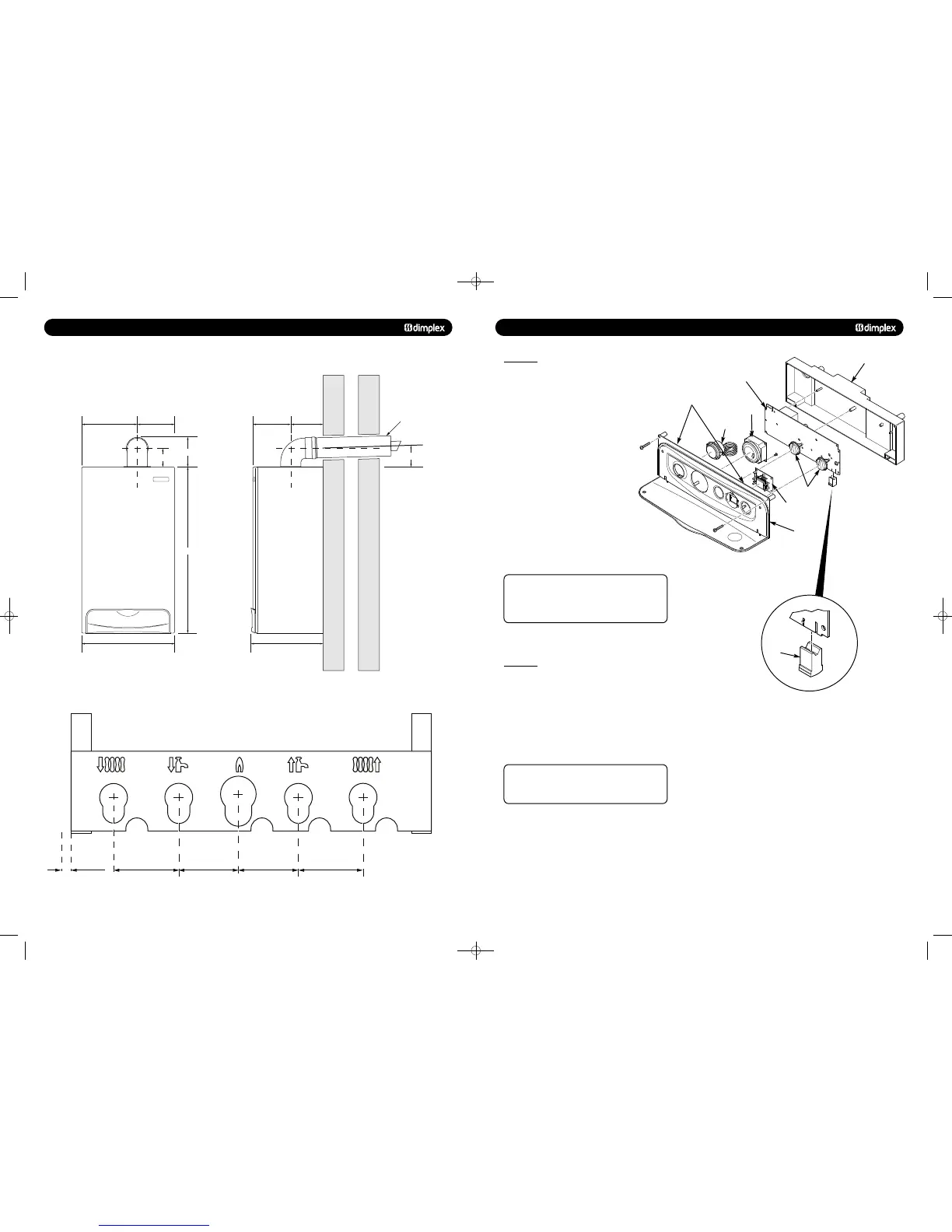
13.0 CHANGING COMPONENTS
13.18 PCB
1. Ensure supply voltage is fully isolated.
2. Undo the screws holding the control box and gently ease
the box forward (Fig. 69).
3. Locate the retaining barbs on the top of the fascia and
unclip them from the control box.
4. Unclip the PCB from the plastic control box.
5. Note the positions of all the connections on the PCB
and disconnect them.
(DO NOT REMOVE THE YELLOW BCC (Fig. 69))
6. Carefully unclip and remove the ribbon cable
from the PCB and withdraw.
7. Fit all the connection plugs to the new PCB
including the ribbon cable, take care not to damage
the PCB.
8. Unless specifically instructed N
to do so by the Dimplex
Service Department, always fit the new BCC if supplied with
the replacement PCB.
Always double check the label on the BCC card to
ensure it is the correct BCC for the boiler model to which it
is being fitted. Never fit an incorrect BCC, as this is
extremely dangerous and could result in serious injury or
death.
9. Reassemble in reverse order, ensuring that the control knob
are reset to their previous positions
© Dimplex Boilers 2008
1. Ensure supply voltage is fully isolated.
2. Dismantle the control box as described above to gain access
to the PCB (Fig. 69).
3. Note the orientation of the existing BCC (if fitted) and
carefully remove by sliding it off the edge of the PCB.
4. Re-fit the new BCC by sliding it onto the edge of the PCB,
ensuring the orientation is correct.
Always double check the label on the BCC card to
ensure it is the correct BCC for the boiler model to which it
is being fitted.
NEVER FIT AN INCORRECT BCC.
5. Reassemble as above.
6. Power up boiler, and briefly press the reset button, wait for
at least 5 seconds and then briefly press the reset button
again.
7. The boiler should now be checked for operation in DHW and
CH modes.
PCB
Facia
Control Box
Retaining Barbs
Pressure
Gauge
Timer
User Interface
Control Knobs
BCC
48pp MANUAL SPREADS 19/10/10 08:36 Page 10