Service Mode automatically stops after 10 minutes
and the boiler returns to normal operation.
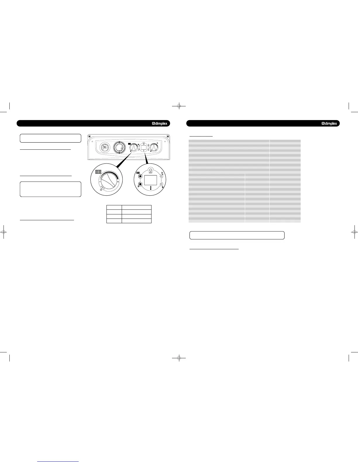
On Dimplex Combi 24, 30 and 38kW boilers, the
maximum gas rate is only available when the boiler is in hot
water mode. Open two or more hot water taps and ensure
that the flow rate is not less than quoted in Table 3.
1. Turn the CH knob fully clockwise - Note the knob will turn
past the maximum temperature mark (Fig. 45).
2. The CH and DHW lights will flash continuously - the boiler is
now running at minimum rate.
1. To exit Service Mode, turn the CH knob anti-clockwise to
the temperature previously set by the customer. The CH and
DHW lights will now stop flashing.
1. Set the boiler into Service Mode at Minimum Rate.
2. Whilst in Service Mode at Min Rate, turn the CH knob to 12
‘O’ clock position and then back to fully clockwise (past the
maximum temperature indicator) within 3 seconds. The boiler
will now run at maximum gas rate for 10 minutes.
11.1 TO SET THE BOILER AT MINIMUM GAS RATE
11.2 TO SET THE BOILER AT MAXIMUM GAS RATE
11.3 TO SET THE BOILER AT MAXIMUM GAS RATE IN
CENTRAL HEATING
Fig. 45 Fig. 46
Comfort +
1
13
2
14
3
15
4
16
5
17
6
18
7
19
8
20
9
21
10
22
1
1
23
1
2
2
4
0
1
0
1
2
bar
3
4
Flow rate (litres/minute)Boiler Model
Combi 24kW
8.0 FLUE OPTIONS
8.10 FLUE LENGTHS
Length supplied in standard kit - horizontal 815mm
Max horizontal length (from boiler to chimney - 60/100mm) 2000mm
Min horizontal length (from boiler to chimney - 60/100mm) 100mm
Max vertical length (from boiler to chimney - 60/100mm) 2000mm
Min vertical length (from boiler to chimney - 60/100mm) 200mm
Length supplied in standard kit - vertical (available in 10m, 20m an 30m length) N/A
Flexitube must be purchased as an accessory to complete the kit (see below)
Flexitube min length 5m
Flexitube max length 30m
Description Part No. Equivalent Length
Horizontal - 60/100 Accessories
Flue extension duct - 500mm 956092 450mm
Flue extension duct - 1000mm (incl. 1 x support bracket) 956093 950mm
93° extension elbow 956091 1550mm
45° extension elbow (pair) 956090 775mm
Air inlet duct - included in kit N/A N/A
Straight adaptor (60/80) - included in kit N/A N/A
91.5° adaptor elbow (80/80) - included in kit N/A N/A
Support bracket - 100mm 840517 N/A
93° flanged elbow - included in kit 956082 N/A
Vertical turret socket 956087 N/A
Flexi tube - 10m 956110 10m
Flexi tube - 20m 956111 20m
Flexi tube - 30m 956112 30m
Straight duct (80) - included in kit N/A N/A
Chimney terminal - included in kit N/A N/A
Note: Equivalent length information only required for coaxial flue parts.
The corrugated (Flexi tube) flue parts are fixed and all parts are required for every application.
21
8.11 Additional Concentric Flue Kit Accessories
The following additional concentric kit accessories are available
as optional extras.
Flue Extension Ducts - 1000 mm (956093) and 500 mm
(956092), (each duct extends the flue length by up to 950
mm and 450 mm respectively).
93° Extension Elbow (956091) - Allows an additional bend in
the flue, and has an ‘equivalent length’ of 1550 mm. This
elbow is mechanically different from the flanged elbow
supplied as standard with the appliance, but has the same
equivalent length.
45° Extension Elbow (956090) - Allows an additional bend in
the flue and has an ‘equivalent length’ of 775 mm.
Vertical Turret Socket (956087) - For use with elevated
horizontal flues and vertical terminals.
Vertical Roof Terminal - For use where an external wall is not
available, or where it is desirable to route the ducts vertically.
For installation details refer to the instructions provided with
the individual flue kits.
These optional kits may be used with the standard flue kits to
produce an extensive range of flue options, providing that the
following rules are strictly obeyed.
a) The maximum/minimum permissible length of the room
sealed flue system are:
Horizontal flue terminal (all orientations)
maximum 10000 mm
Horizontal flue terminal (rear exit)
minimum 250 mm
Vertical flue terminal maximum 12000 mm
Vertical flue terminal minimum 600 mm
The ‘equivalent’ flue length must not exceed the maximum
values stated.
b) The standard terminal must be fitted horizontally; horizontal
ducts must have a continuous fall towards the appliance of
1.5° to 3°. This ensures condensate runs back into the
appliance from the flue system. The vertical terminal must
always be used if a vertical outlet is required.
c) The concentric flue system must use either a flanged elbow
or a vertical flue turret socket at the entry/exit to the
appliance.
d) All joints must be correctly made and secured in accordance
with the installation instructions. When cutting ducts, avoid
swarf, uneven and sharp edges to maintain duct integrity.
Refer to Fig. 19 & 20 to determine which option kits are
required before commencing the installation. Instructions for
installing the appliance with a horizontal flue and straight
extension ducts are included in the main text of these
instructions (section 9.5).
48pp MANUAL SPREADS 19/10/10 08:36 Page 21
 Loading...

