8.0 FLUE OPTIONS
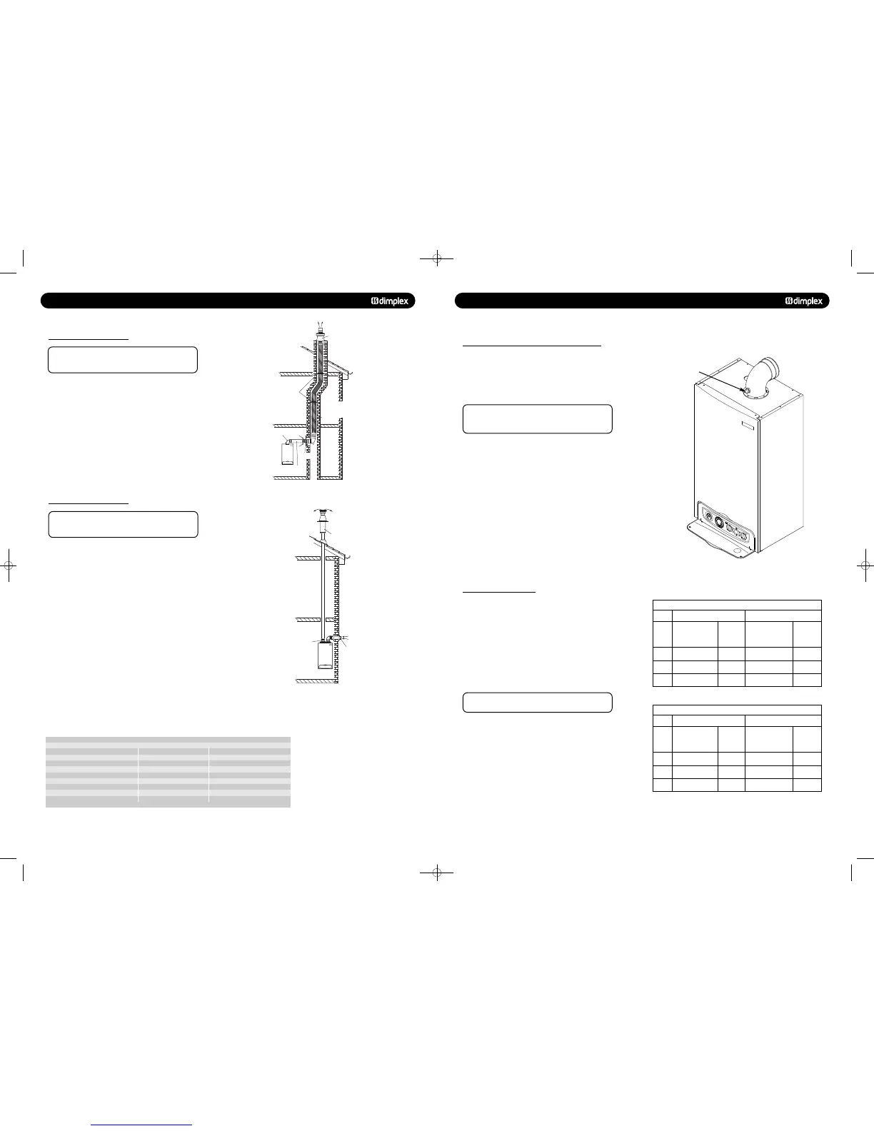
8.8 Kit E Chimney Flue Liner Kit
(B23) - Part no. 956082
Note:
Dimplex Combi 38 - Maximum flue length 21m, and 30m
for all other appliances.
This kit is suitable for open flue application in accordance with
BS5440 where a room sealed flue installation is impractical.
The kit comprises of a flue adaptor from the appliance to the
chimney, a flexible plastic flue liner with connection parts and
chimney terminal (see Fig. 27). Where an open flue system is
used, then an air vent must be provided in the same room or
internal space as the flue duct air inlet, see section 7.3.
For installation details refer to the flue kit instructions.
Maximum flue resistive length = 30m.
A flue system can be built up from the components detailed in
table 8.10, but the total flue resistance must not exceed the
maximum stated.
8.9 Kit F: Twin Flue System
(C53) - Part no. 956080
Note:
Dimplex Combi 38 - Maximum flue length 21m, and 30m
for all other appliances.
This flue system kit is designed for installations where the air
intake position is different than the flue duct exit point. The kit
comprises of a twin adaptor from which the air intake is taken
from the adjacent outside wall (see Fig. 28) and the flue duct
is routed vertically through the roof.
It has to be noted that the flue duct is under pressure when
the appliance is in operation and the duct can leak poisonous
carbon monoxide if the duct components are not correctly
assembled. It is n
recommended to route the flue duct
through living space areas, i.e. bedrooms, living rooms etc.
For installation details refer to the instructions provided with
the twin flued kit.
For C53 flue systems the terminal for the supply of
combustion air and for the evacuation of combustion products
shall not be installed on opposite walls of the building.
Maximum flue resistance permitted for a twin flued system
= 52 Pa
Minimum flue resistance permitted for a twin flued system
= 23.5 Pa
Centralising brackets
Chimney terminal
93 flanged elbow (concentric)
with sampling point
Ø60/100mm concentric
chimney adaptor pipe.
In replacement installations,
the chimney has to be
cleared of debris and
all flue parts.
Chimney
plate
Flexible corrugated plastic flue liner
Ø80mm according to EN 14471
Max. length 30m.
Min. length 5m.
KIT E
Chimney flue liner kit - Part no. 956082
Flue Component Flue Resistance (Pa) Part Number
Twin Flue Adaptor (required) 9.5 -
Air Inlet Terminal (required) 3 -
Chimney Terminal (required) 0.5 -
80 mm dia straight duct 1 metre 1 956101
80 mm dia straight duct 2 metre 2 956102
90° Elbow (80/80) 8 956100
45° Elbow (80/80) 4 956099
A flue system can be built up from the components detailed in the table, but the total flue
resistance must not exceed the maximum stated.
Ø80mm air intake
Split flue system
Roof terminal with pitched
roof flashing kit.
If the flue pipe passes
through compartment
from wall/floors, the
requirements set out
in Building Regulations
Part B must be followe
d.
Ø80mm twin adaptor
with sampling point.
If the flue pipe passes
through habitable rooms
within the same dwelling,
the flue pipe must be
routed through vented
ducts.
The flue resistance for the
following accessories has
to be considered.
Ø80mm flue extension
90 elbow
45 elbow
Split pipe vertical
flue outlet kit -
Part no. 956080
Kit F
!
12.0 SERVICING AND MAINTENANCE
12.1 ROUTINE SERVICING AND ALL MAINTENANCE THAT
INVOLVES THE EXCHANGE OF PART OF THE
COMBUSTION CIRCUIT
1. During routine servicing, e.g. an annual service check, and
after all maintenance that involves the exchange of parts of
the combustion circuit, we recommend that (in this order) the
integrity of the full flue system and combustion circuit seals,
the inlet gas pressure, gas rate and combustion performance is
verified.
The combustion circuit on this appliance comprises
of the PCB, fan, air/gas ratio valve, burner, burner door,
combustion box door, injector and flue system.
2. To ensure continued safe and efficient operation of the
appliance it is recommended that the boiler is serviced at least
annually. Servicing must be performed by a competent person.
BS 7967-1 gives guidance on identifying and managing
sources of fumes, smells, spillage/leakage of combustion
products and carbon monoxide detector activation.
On any service visit always check;
a. Condition of flue system, both air and combustion products
ducts.
b. Condition of seals and joints.
c. For evidence of leakage of combustion products.
d. For evidence of heat staining.
e. For operation at maximum heat input.
f. The general condition of the boiler and its components.
1. Combustion checks must be carried out with the outercase
fitted.
2. Remove the sampling cap from the boiler flue elbow or
boiler vertical flue adaptor.
3. Insert the probe from the portable electronic combustion
analyser into the sampling point.
4. With the appliance operational, connect the flue gas
analyser to the flue sampling point as shown in Fig. 47.
The outercase must be fitted for all combustion
checks.
5. With the boiler at minimum rate and then at maximum rate
(allowing the combustion to stabilise at each rate before taking
a reading) carry out the combustion checks as follows:
COMBUSTION CHECKS AT MINIMUM RATE
6. The combustion values at minimum gas rate and maximum
gas rate must be checked using a suitable calibrated flue gas
analyser. Further guidance is detailed in BS7967 parts 1 to 4.
7. Set the boiler into Service Mode at Min Rate
(see section 11.1).
8. Check the Carbon Monoxide (CO) and Carbon Dioxide (CO
2
)
readings are within the range quoted in the tables opposite
(Table 1).
© Dimplex Boilers 2008
C
o
m
f
or
t
+
1
13
2
1
4
3
1
5
4
1
6
5
1
7
6
1
8
7
1
9
8
2
0
9
2
1
1
0
2
2
1
1
2
3
1
2
2
4
0
1
0
1
2
b
a
r
3
4
Carbon
Monoxide
CO
p.p.m
0 - 40
0 - 40
0 - 30
Carbon
Dioxide
CO
2
%
8.2 - 8.6
8.7 - 9.1
8.3 - 8.7
Carbon
Monoxide
CO
p.p.m
0 - 40
0 - 40
0 - 40
Carbon
Dioxide
CO
2
%
10.2 - 10.6
10.2 - 10.6
10.4 - 10.8
Carbon
Monoxide
CO
p.p.m
40 - 120
40 - 120
40 - 120
Carbon
Dioxide
CO
2
%
8.8 - 9.2
9.1 - 9.5
8.9 - 9.3
Carbon
Monoxide
CO
p.p.m
80 - 160
100 - 180
70 - 150
Carbon
Dioxide
CO
2
%
10.5 - 10.9
10.7 - 11.1
10.5 - 10.9
48pp MANUAL SPREADS 19/10/10 08:36 Page 20
 Loading...

