6.0 SYSTEM DETAILS
6.4 SYSTEM FILLING AND PRESSURISING
1. A filling point connection on the central heating return
pipework must be provided for initial filling and pressurising
and subsequent topping up of the system.
A filling loop is provided loose with the boiler
2. The filling method adopted must comply with all relevant
water supply regulations and use approved equipment.
3. Further details are given in;
for GB: Guidance G24.2 and recommendation R24.2 of the
Water Regulations Guide.
for IE: the current edition of I.S. 813 “Domestic Gas
Installations”.
4. The sealed primary circuits may be filled or topped up using
a temporary connection between the circuit and a supply pipe,
provided a ‘Listed’ double check valve or some other no less
effective backflow prevention device is permanently connected
at the inlet to the circuit and the temporary connection is
removed after use.
6.5 EXPANSION VESSEL (CENTRAL HEATING ONLY)
1. The appliance expansion vessel is pre-charged to 1 bar.
Therefore the minimum cold fill pressure is 2 bar. The vessel is
suitable for correct operation for system capacities up to 84
litres. For greater system capacities an additional expansion
vessel must be fitted.
For GB refer to BS 7074 Pt 1.
For IE, the current edition of I.S. 813 “Domestic Gas
Installations”.
6.6 PRESSURE RELIEF VALVE
1. The pressure relief valve is set at 3 bar, therefore all
pipework, fittings, etc. should be suitable for pressures in
excess of 3 bar and temperature greater than 100°C.
2. The pressure relief discharge pipe should be not less than
15mm diameter, run continuously downward, and discharge
outside the building, preferably over a drain. It should be
routed in such a manner that no hazard occurs to occupants or
causes damage to wiring or electrical components. The end of
the pipe should terminate facing down and towards the wall.
NOTE: Boiling water/steam could discharge from the pipe,
therefore it should be terminated away from windows and
doors.
DHW
Mains
Inlet
CH
Return
Pressure
Relief
Discharge
Pipe
Temporary
Loop
Stop
Val ve
Stop
Val ve
Double
Check
Val ve
GasDHW
Outlet
CH
Flow
Condensate
Dimplex Combi Range Available Head
Flow L/Min
Available Head M
7.00
0 5 10 15 20
25
6.00
5.00
4.00
3.00
2.00
1.00
0.00
Dimplex Combi
Expansion Vessel
Pressure
Relief Valve
Vessel charge and initial
system pressure
Total water content of
system using 8 litres
capacity expansion
vessel supplied with
appliance
For systems having a
larger capacity multiply
the total system capacity
in litres by this factor to
obtain the total minimum
expansion vessel capacity
required in litres
bar
litres
0.5
96
0.75
84
0.093
1.0
73
1.5
50
Fig. 6
Fig. 9
NOTE: Do not use the pressure relief valve to drain the system, because dirt
and debris could prevent the valve seating correctly.
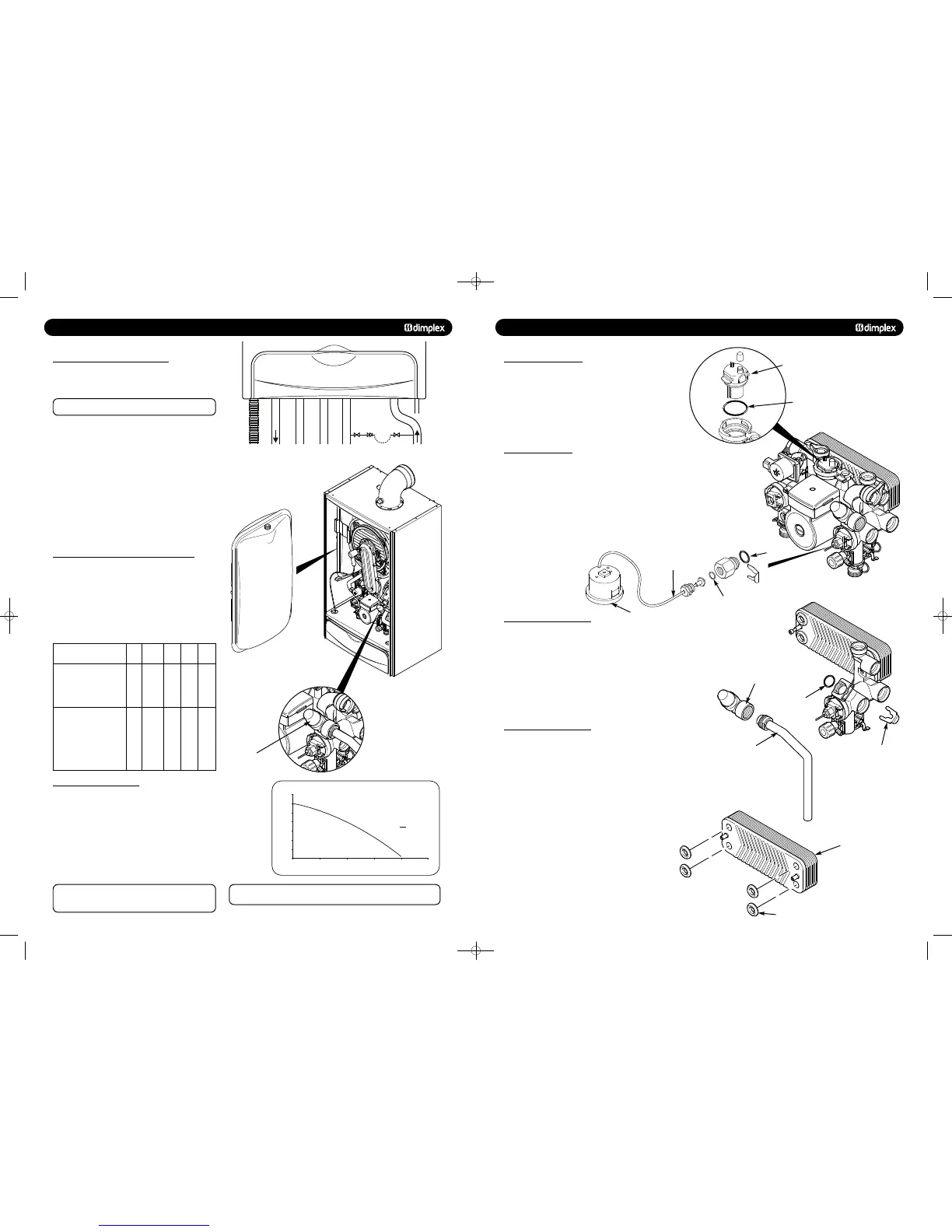
13.0 CHANGING COMPONENTS
13.12 AUTOMATIC AIR VENT
1. Drain the primary circuit and rotate the automatic air vent
1
/
4
turn and remove from the pump body.
2. Examine the ‘O’ ring seal, replacing if necessary, and fit it to
the new automatic air vent.
3. Reassemble in reverse order.
© Dimplex Boilers 2008
1. Drain the primary circuit and undo the nut on the pressure
gauge capillary.
2. Examine the ‘O’ ring seal, replace if necessary.
3. Unclip the facia from the control box
4. Lever the barbs securing the gauge to remove the gauge
from the control box (Fig. 64).
5. Reassemble in reverse order.
13.14 PRESSURE RELIEF VALVE
1. Drain the primary circuit.
2. Disconnect the discharge pipe from the valve. Ease off the
retaining clip (Fig. 65).
3. Note the orientation of the valve, rotate it and withdraw it
from the manifold.
4. Fit the new valve and ‘O’ ring and set to the previously
noted orientation. Reassemble in reverse order.
Automatic Air Vent
‘O’ Ring
Pressure Gauge
Pressure
Relief Valve
Retaining Clip
‘O’ Ring
Discharge Pipe
Capillary
‘O’ Ring
‘O’ Ring
13.15 PLATE HEAT EXCHANGER
1. Drain the primary circuit.
2. While supporting the heat exchanger undo the two screws
securing it to the plastic manifold.
3. Hold the heat exchanger at the right hand side and rotate it
upwards. Withdraw it from the boiler over the gas valve.
4. There are four seals between the manifolds and heat
exchanger which may need replacement (Fig. 65).
5. Ease the seals out of the manifold. Replace carefully,
ensuring that when the seal is inserted into the manifold it is
parallel and pushed fully in.
6. When re-assembling ensure that the ‘V’ pattern on the heat
exchanger points to the right hand side of the boiler.
7. Reassemble in reverse order.
Plate Heat
Exchanger
Seal
48pp MANUAL SPREADS 19/10/10 08:36 Page 12
 Loading...

