Global Link Ultra E Lock Instructions
March 2019 Page 7
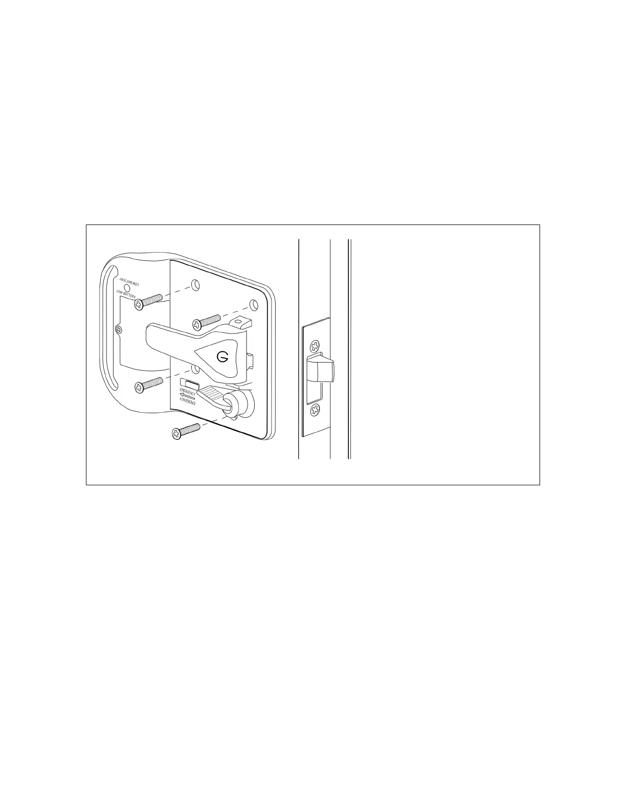
5. Refer to the figure and position the interior lock assembly on the door, ensuring:
The deadbolt post is inserted in the red deadbolt lever so that the lever operates
the deadbolt.
The interior handle post is positioned on the door-edge side of the latch tab so
that the handle operates the latch.
The 3 screw posts on the interior housing align with the 3 screw bosses on the
exterior housing. Do not overtighten the screws.
6. Secure the lock housings with the 4 #8-32 x 7/8” oval head screws provided.
7. Ensure the handle operates the latch and the red deadbolt lever operates the deadbolt.
Figure 5: Installing the Interior Assembly
8. Check that the strike plate is properly aligned with the lock. If necessary, adjust alignment
to ensure:
The lock functions properly. The plunger should extend fully into the strike plate
when the door is locked.
The door opens and closes smoothly and seals completely when closed.