15 0020008154A
3 Flue Location and Ventilation
Diagram 3.6
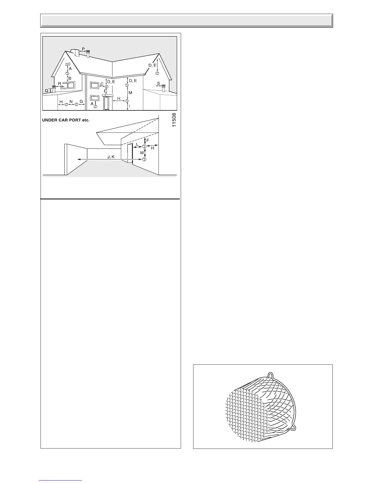
TERMINAL GUARD
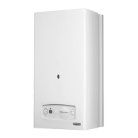
3.4 Terminal Position
The minimum acceptable siting dimensions for the terminal
from obstructions, other terminals and ventilation openings are
shown in diagram 3.5. For Ireland the minimum distances for
flue terminal positioning must be those detailed in I.S.813
"Domestic Gas Installations".
The terminal must be exposed to the external air, allowing free
passage of air across it at all times.
Being a condensing boiler some pluming may occur from the
flue outlet. This should be taken into consideration when
selecting the position for the terminal.
H* and J* See diagram 3.5 . These dimensions comply with
the building regulations, but they may need to be increased to
avoid wall staining and nuisance from pluming depending on
site conditions.
Increased siting flexibility can be achieved by using the Glow-
worm Plume Management Kit, A2044000 (black) or A2044100
(white).
NOTE: If necessary it is permitted to increase the terminal
protrusion through the outside wall to greater than the minimum
dimension of 87mm but no more than 600mm, see diagram 1.1.
Carports or similar extensions of a roof only, or a roof and one
wall, require special consideration with respect to any openings,
doors, vents or windows under the roof. Care is required to
protect the roof if made of plastic sheeting. If the carport
comprises of a roof and two or more walls, seek advice from the
local gas supply company before installing the boiler.
H* and J* See diagram 3.5 . These dimensions comply with
the building regulations, but they may need to be increased to
avoid wall staining and nuisance from pluming depending on
site conditions.
3.5 Terminal Guard
A terminal guard is required if persons could come into contact
with the terminal or the terminal could be subject to damage.
If a terminal guard is required, it must be positioned to provide
minimum of 50mm clearance from any part of the terminal and
be central over the terminal.
The guard should be similar to that shown in diagram 3.6.
A suitable guard is manufactured by: -
Tower Flue Components
Morley Rd.
Tonbridge
Kent
TN9 1RA.
Size: 280mm x 280mm x 270mm.
Diagram 3.5
MINIMUM SITING DIMENSIONS FOR
FANNED FLUE TERMINALS POSITION MM
HORIZONTAL FLUES
A DIRECTLY BELOW AN OPENING, AIR BRICK,
OPENING WINDOWS 300
B ABOVE AN OPENING, AIR BRICK,
OPENING WINDOWS 300
C HORIZONTALLY TO AN OPENING,
AIR BRICK, OPENING WINDOWS 300
D BELOW GUTTER, DRAIN/SOIL PIPE 25
E BELOW EAVES 25
F BELOW A BALCONY OR CAR PORT 25
G FROM VERTICAL DRAIN PIPES AND
SOIL PIPES 25
H FROM INTERNAL/EXTERNAL CORNERS 25
H TO A BOUNDARY ALONGSIDE THE
TERMINAL 300
I ABOVE ADJACENT GROUND OR
BALCONY LEVEL 300
J FROM SURFACE OR A BOUNDARY
FACING THE TERMINAL 600
K FACING TERMINALS 1200
L FROM OPENING (DOOR/WINDOW)
IN CAR PORT INTO DWELLING 1200
M VERTICAL FROM A TERMINAL 1500
N HORIZONTALLY FROM A TERMINAL 300
VERTICAL FLUES
P FROM ANOTHER TERMINAL 600
Q ABOVE ROOF LEVEL 300
R FROM ADJACENT OPENING WINDOW 1000
S FROM ADJACENT WALL TO FLUE 300
*
*

 Loading...