27 0020008154A
10 Electrical Connection
Diagram 10.3
Diagram 10.5
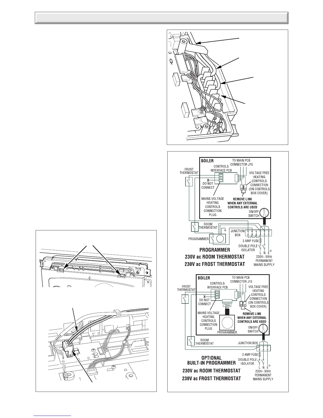
10.3 Mains Voltage System Controls
WARNING: UNDER NO CIRCUMSTANCES MUST ANY
MAINS VOLTAGE BE APPLIED TO ANY OF THE TERMINALS
ON THE VOLTAGE FREE HEATING CONTROLS
CONNECTION PLUG.
Remove the MAINS VOLTAGE HEATING CONTROLS
CONNECTION PLUG from the fittings pack and install on the
control interface PCB as follows.
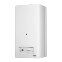
Gain access to the control and user interface PCB's by unclipping
the fascia panel and hinging forward, see diagram 10.3.
Route the system controls cable and connect to the plug
, see
diagram 10.3.
Insert plug onto controls interface PCB, see diagram 10.3.
Close the fascia panel and remove the screws to open the rear
cover of control panel, see diagram 10.1.
Secure the system control cable in the strain relief, and thread
the cable through rear of the control panel and out of the cables
exit, see diagram 10.4.
Close and secure rear cover of control panel.
Remove the wire link from the voltage free heating controls
connector, see diagram 10.1.
Connect system controls as diagram 10.5.
External controls should be fitted in accordance with the rules
in force.
10.4 Electrical Connections - Testing
Carry out preliminary electrical system checks as below:
1. Test insulation resistance to earth of mains cables.
2. Test the earth continuity and short circuit of cables.
3. Test the polarity of the mains.
PLUG
SYSTEM CONTROLS CABLE
( MAINS VOLTAGE)
RETAINING
LATCHES
11472
11408
Diagram 10.4
CABLE
EXIT
SYSTEM
CONTROLS
CABLE
12441
12440
12406
MAINS
CABLE
STRAIN
RELIEF

 Loading...