49 0020008154A
Diagram 14.25
14 Replacement of Parts
Diagram 14.26
14.38 Access to Switches, User Interface and
Programmer
For access, refer to section 14.1.
Release the front of the fascia by carefully prising up the two
retaining latches, see diagram 14.26.
Do not allow the front of the fascia to swing down and be loosely
held by the electrical connections to the mains/reset switch,
user interface and clock. Either remove the connections or
support the fascia.
14.39 Programmer (if fitted)
Refer to section 14.38 for access.
Remove electrical plug.
Undo two securing screws and withdraw programmer.
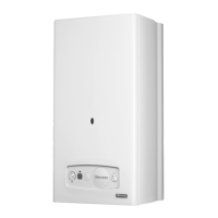
14.40 Mains Reset Switch
Refer to section 14.38 for access.
Remove the switch retaining screw.
Remove switch from housing, see diagram 14.25.
Remove electrical leads.
14.41 Mains Reset Knob
Refer to section 14.38 for access.
Remove actuator by springing back retaining clips, see diagram
14.25.
Spring back knob retaining clips and push knob out from the
back.
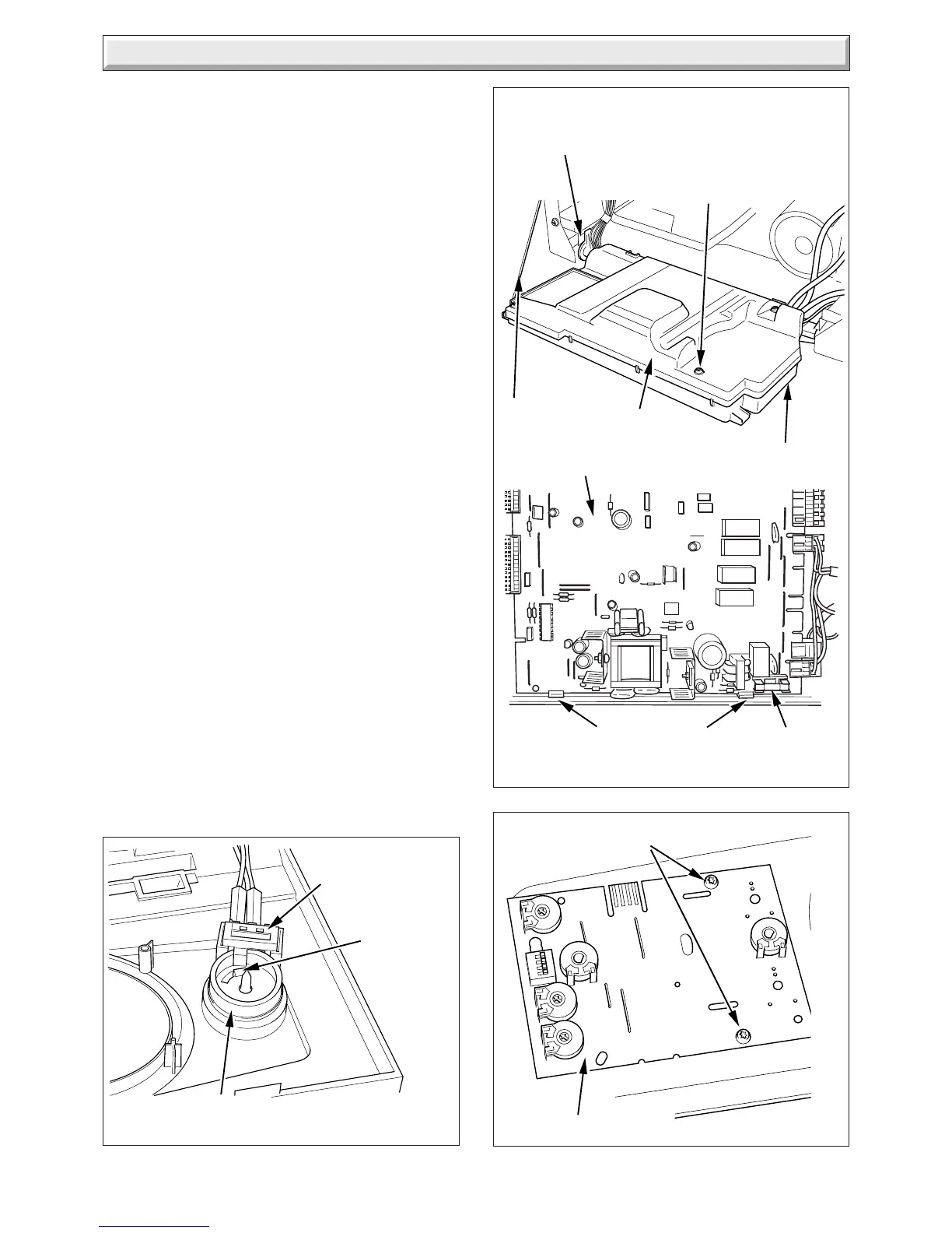
14.42 User Interface
Refer to section 14.38 for access.
Remove electrical plug.
Remove the securing screws, see diagram 14.27.
Withdraw the board.
When replacing the board refer to instructions supplied with
replacement PCB on setting it up.
9808
REAR PANEL
TORX
SCREWS (3)
CONTROL BOX
PCB RETAINING
CLIPS
MAINS/RESET
KNOB
MAINS/RESET
SWITCH
KNOB
RETAINING
CLIPS
RETAINING
CORD
RETAINING
SLOTS
Diagram 14.27
USER INTERFACE
SECURING SCREWS
11416
11417
12411
FUSE
MAIN PCB

 Loading...