19 0020008154A
6 Installation Preparation
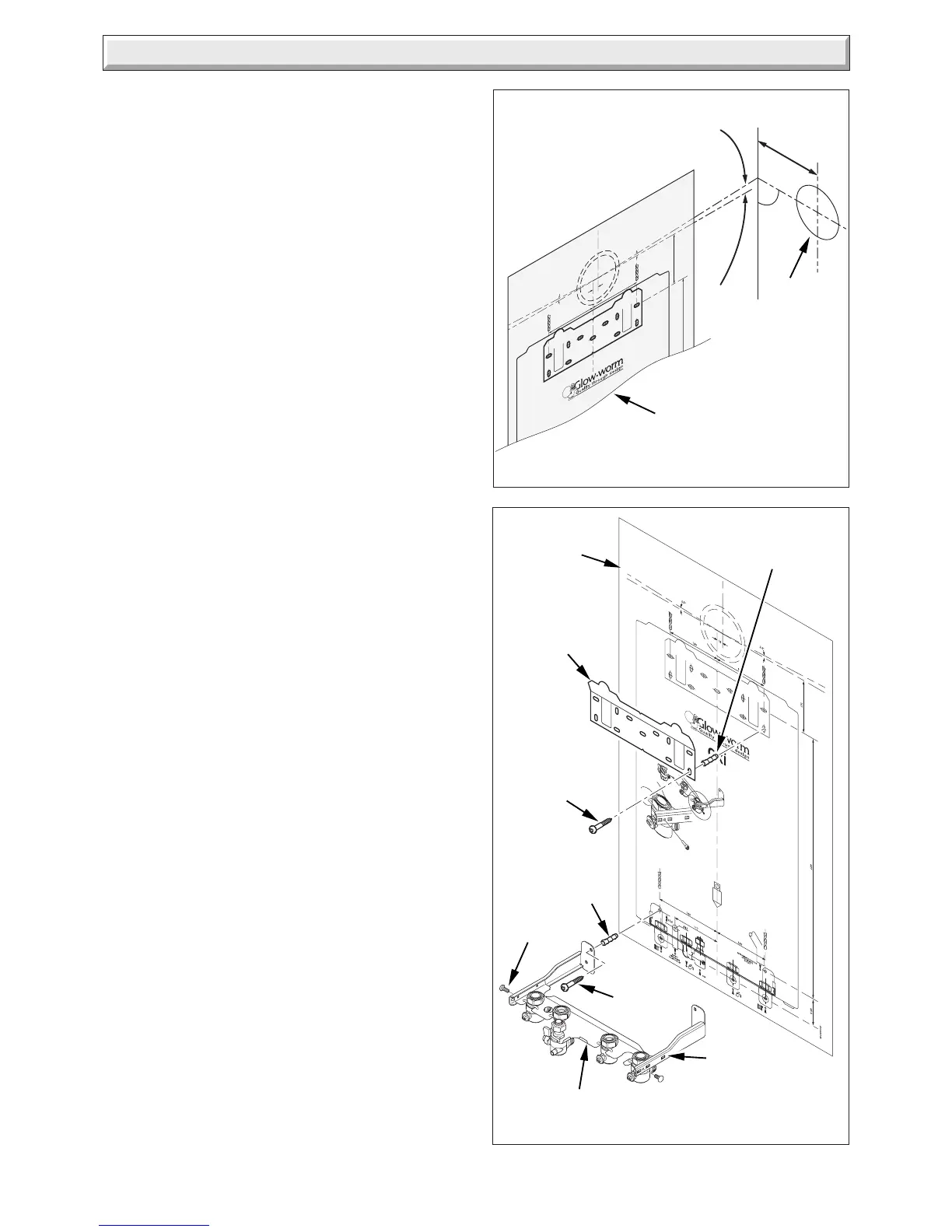
6.2 Wall Template
Take the wall template from the fixing jig pack and place in the
desired position on a flat wall, giving due consideration to boiler
clearances, see section 2, and the flue you are fitting.
6.3 Flue Hole Cutting
The standard horizontal flue is designed with an internal fall
of 44mm/metre towards the boiler for disposal of condensate.
If the standard flue length alone is being used then the flue hole
of diameter 105mm can be cut in the position marked on the wall
template.
For standard side flues the horizontal flue centre line on the
wall template should be extended to the side wall, and the
vertical centre of the flue hole marked at 176mm from the back
wall.
For installations with external access, a 105mm diameter core
drill can be used.
For installations with internal access only a 125mm diameter
core drill should be used.
When using extension pipes with the horizontal rear flue, a core
drill size of 125mm should be used to allow the extension pieces
to slope at 44mm/metre (2.5°) towards the boiler.
For extended side flues, the flue hole centre should be
determined by extending the dashed inclined line on the template
to the side wall. This dashed line is drawn at 44mm/metre (2.5
o
)
rise from the boiler. Where this line reaches the side wall, a
horizontal line should be marked. The vertical centre line of the
flue should then be marked at 176mm from the back wall, see
diagram 6.2.
To allow for the flue passing through the wall at this angle a
125mm hole should be drilled irrespective of internal or external
installation.
Remove the wall template whilst drilling the flue hole.
6.4 Fixing Jig and Hanging Bracket
Reposition the wall template over the flue hole and mark the
position of the fixing holes for the jig and the hanging bracket,
see diagram 6.3.
Drill the four fixing holes, 2 for the hanging bracket and 1 each
for the top hole of the fixing jig wall brackets and insert suitable
wall plugs.
If gas and/or water pipes are to be connected through the rear
wall, the holes must be drilled as marked on the wall template
prior to securing the fixing jig.
Secure the fixing jig wall brackets to the wall using suitable
screws.
NOTE: Due to the varied site conditions we do not supply fixings
and advise that the installer should supply those which are
suitable.
Locate the jig plate between the wall brackets and secure with
the No. 8 self tapping fixing screws supplied in the fittings pack.
130
130
16
127
2.5
°
2.5°
Diagram 6.2
12075
WALL
TEMPLATE
EXTENDED SIDE FLUE
Ø 125
90°
176
2.5° 44mm/metre
Inclined Extended
flue length
Standard
flue length
Horizontal
HANGING
BRACKET
SCREW
(2 OFF)
SCREW
Diagram 6.3
12049
WALL
PLUG
SCREW
WALL
TEMPLATE
FIXING JIG
PLATE
FIXING JIG
WALL BRACKETS
(2 OFF)
(Handed as shown)
WALL
PLUG
 Loading...


