42
0020008154A
14 Replacement of Parts
14.12 Heat Exchanger
Refer to Manual Handling section on page 5.
For access, refer to section 14.1.
Refer to section 12.3 for removal of the fan, gas valve and
burner assembly.
Drain the boiler heating circuit, see section 12.9.
Drain the boiler hot water circuit, see section 12.10.
Remove the clip securing the clear condense pipe to heat
exchanger.
Pull to remove the clear condense pipe out of the bottom of the
heat exchanger.
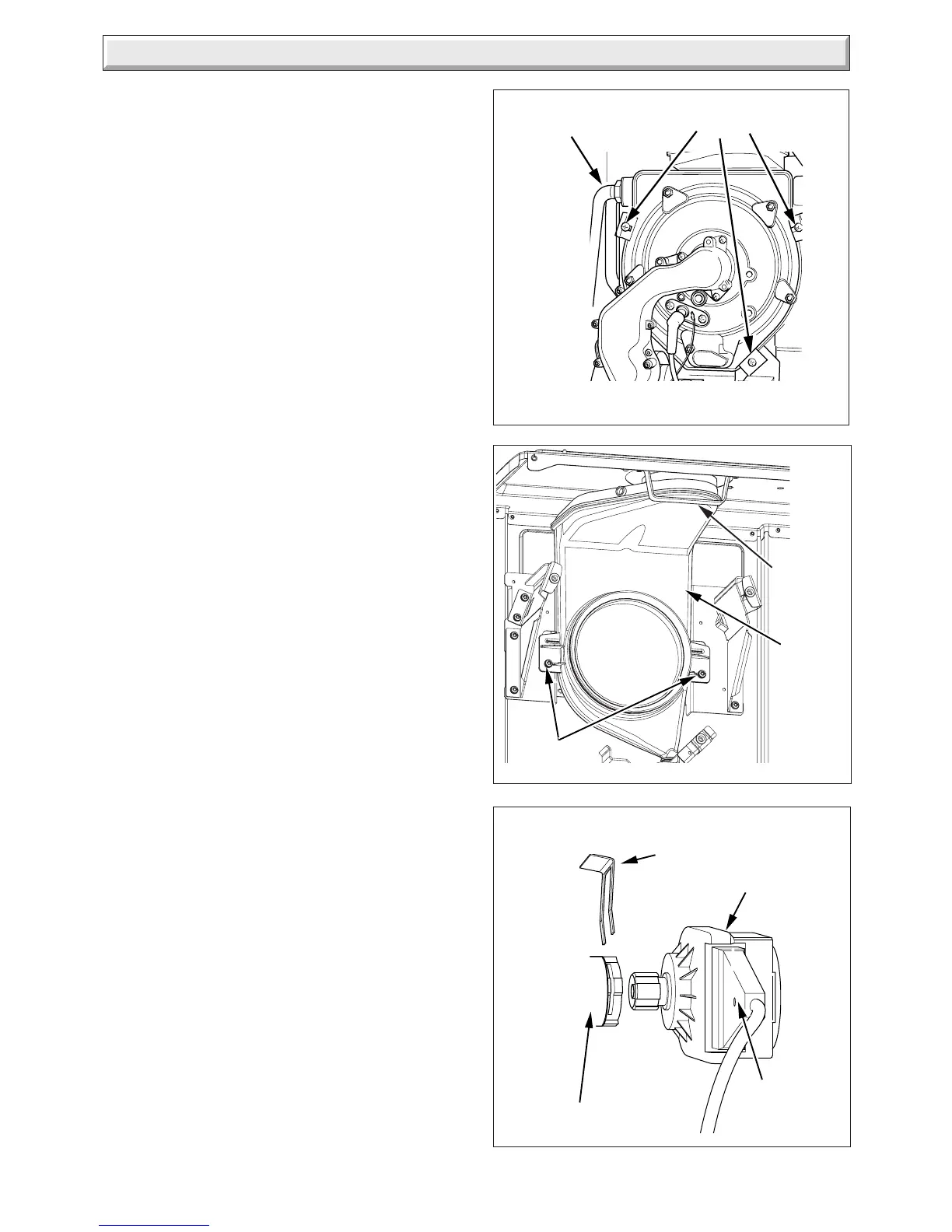
Undo the two nuts of the flow and return pipes from the heat
exchanger.
Move the pipes away from the heat exchanger.
Loosen the three heat exchanger securing screws and clamps
(two at the top and one at the bottom) to remove the heat
exchanger, see diagram 14.9.
CAUTION: There will be water in the heat exchanger.
Remove condense pipe connector from bottom of heat
exchanger.
Carefully ease heat exchanger out.
14.13 Flue Hood
For access, refer to section 14.1.
Remove heat exchanger as per section 14.12.
Remove the two securing screws and pull the flue hood down
and away from the flue hood bracket and flue elbow, see
diagram 14.10.
14.14 Diverter Valve Motor
For access, refer to section 14.1.
Refer to diagram 14.11.
Remove the electrical plug.
Remove the retaining clip.
Ease the diverter valve motor from its housing and remove.
Diagram 14.9
FLOW AND
RETURN PIPE
NUTS
SECURING SCREWS
AND CLAMPS
Diagram 14.10
FLUE
HOOD
BRACKET
SECURING
SCREWS
10066
DIVERTER VALVE
MOTOR
DIVERTER VALVE
Diagram 14.11
ELECTRICAL
PLUG)
RETAINING CLIP
(NOTE ORIENTATION)
11602
11490
FLUE
HOOD
 Loading...


