20
0020008154A
7.1 System Connection
The system can now be connected without the boiler being
mounted. All water and gas connections are on the fixing jig with
the exception of the condense drain and safety discharge, the
positions of these are shown on the wall template.
The gas supply pipe must be chased into the wall if routed up
the back of the boiler.
A Vertical Plumbing Kit can be used to route the central heating
or DHW pipes, see section 1.6.
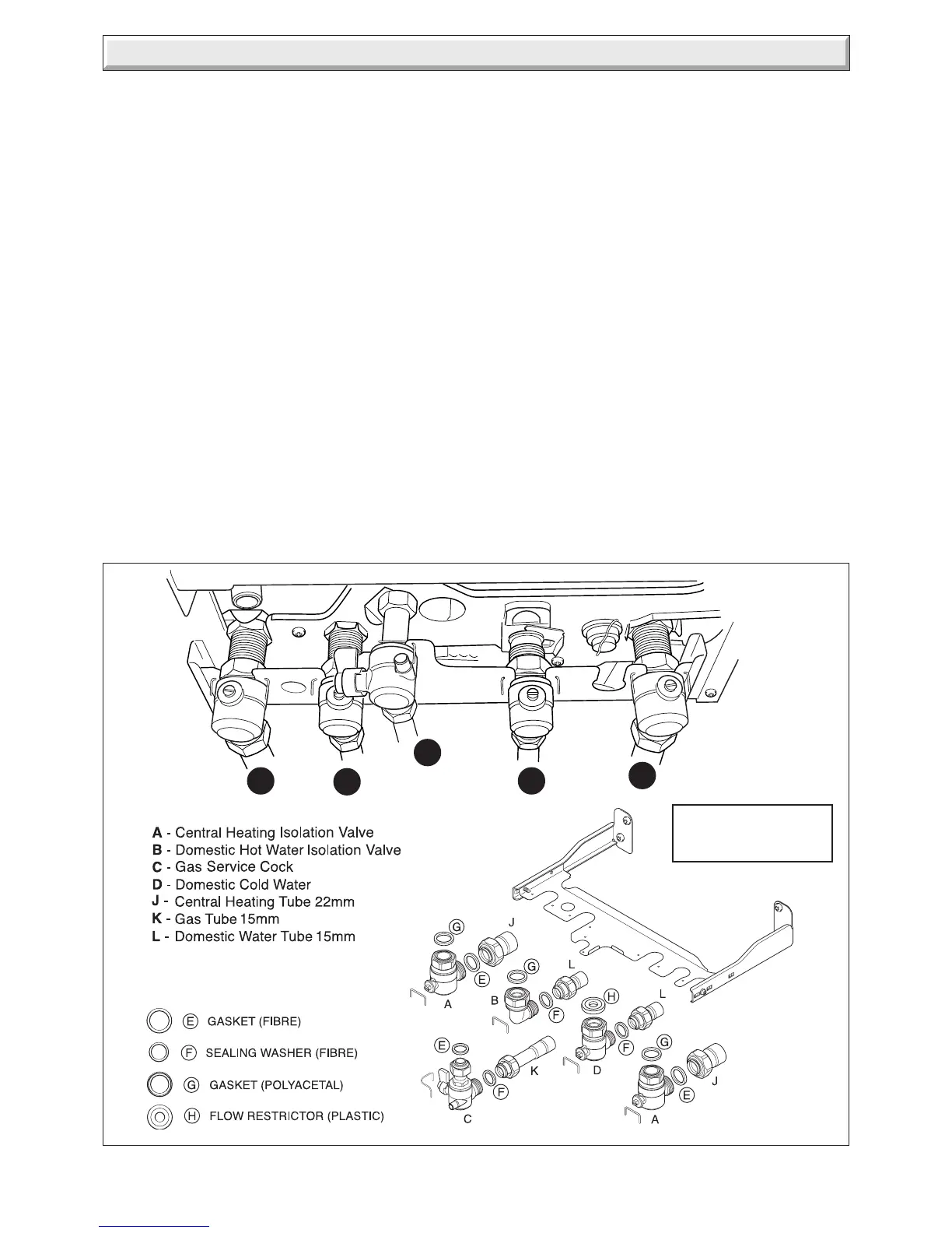
Make connections to fixing jig, gas, water and heating cocks
with the tube assemblies supplied in fixing pack as shown in
diagram 7.1.
7.2 Gas Connection
Before connection check supply of local gas.
Refer also to section 1.2.
Do not subject the gas service cock to heat.
Fit the sealing washer into the union nut and make good the
connection to the gas service cock on the wall fixing jig, see
diagram 7.1.
Make sure the on / off lever is accessible.
The whole of the gas installation, including the meter, should be
inspected, tested for soundness and purged in accordance with
the current issue of BS6891 and in IE the current edition of
I.S.813 "Domestic Gas Installations".
7 Gas/Water & Appliance Connection
7.3 Water Connections
Flush out the domestic hot water and the heating systems
before connecting to the boiler.
Make the connections to the domestic hot water and heating
systems by fitting the sealing washers into the securing nuts
and make good the connection to the isolating valves on the
fixing jig, see diagram 7.1.
Do not subject the isolation valves to heat.
Make sure the drain point is accessible, refer diagram 12.11.
7.4 Appliance Connection
IMPORTANT: With regards to the Manual Handling Operations,
1992 Regulations, the following lift operation exceeds the
recommended weight for a one man lift, refer to Manual Handling
section, on page 5.
The appliance will contain a small amount of water, place a
water container beneath the boiler connections before removing
the protective caps.
Position gasket/sealing washers and cold water inlet flow
restrictor supplied in the fittings pack, as shown in diagram 7.1.
Lifting the boiler into position, lean the top of the boiler slightly
to the wall and position just above the hanging bracket. Lower
the boiler slowly and engage onto the hanging bracket.
Pivot the boiler to engage the fixing jig connections, ensuring
that the previously positioned washers /gaskets and DHW flow
restrictor are not disturbed, see diagram 7.1.
Make good the final connections.
Diagram 7.1
12349
A
B
D
C
12347
ALL ISOLATION
VALVES ARE SHOWN
IN CLOSED POSITION
A
 Loading...


