50
0020008154A
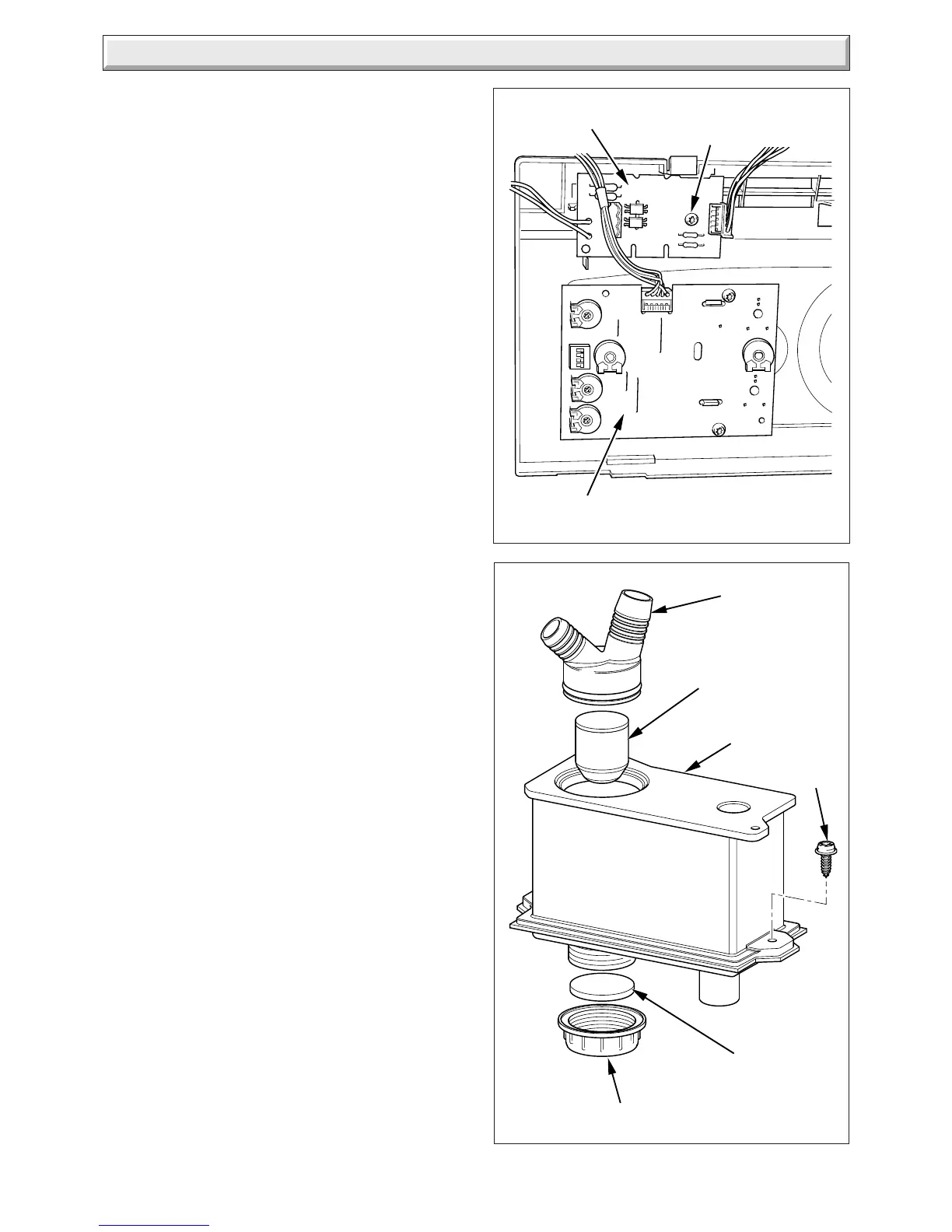
14 Replacement of Parts
Diagram 14.28
230V CONTROLS
INTERFACE BOARD
USER
INTERFACE
RETAINING
SCREW
11419
Diagram 14.29
9948
CAP
SEAL
SIPHON
ADAPTER
CONDENSE
TRAP
FLOAT
SCREW
14.43 Main PCB
For access, refer to section 14.1.
Hinge down the control box.
Remove TORX screws and unhook the rear panel.
Remove the electrical connections to the PCB.
Prise back the two PCB retaining clips and withdraw the PCB,
see diagram 14.26.
When refitting the rear panel ensure the leads are not trapped,
refer to diagram 14.3.
14.44 Control Box
For access, refer to section 14.43.
Remove relevant plugs and connectors, refer to wiring diagram
13.1.
Withdraw grommets and leads so they are hanging loose.
Unthread the retaining cord and remove the control box by
drawing it outwards away from its retaining slots, see diagram
14.26.
14.45 Fuse, Main PCB - Control Box
For access, refer to section 14.43.
The fuse is located at bottom right hand side of the PCB, see
diagram 13.1 or 14.26.
14.46 230V Controls Interface
For access, refer to section 14.38.
Disconnect the electrical connection from the 230V controls
interface board and the electrical connection from the Main
PCB.
Remove the 230V controls interface retaining screw.
Remove the 230V controls interface board, see diagram 14.28.
 Loading...


