0020117819_01 - 05/11 - Glow-worm
- 14 -
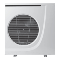
8 Installing the command unit
• Make sure that the materials used for performing the
installation are compatible with those of the appliance.
• Determine the place of assembly. See the chapter "Location".
3
3
1
1
4
2
Key
1 Mounting screw
2 Wall support
3 Rawlplug
4 Electric terminal block
• Separate the command unit from the wall support (3).
• Pass the electrical connection cables through the hole on the
left of the connector and connect them onto terminal (4). See
the chapter "Installation examples".
• Position the support (3) on a wall.
• Drill holes for the fi xing screws in accordance with the 2 fi xing
holes on the wall support (3).
• Insert the rawlplugs (2) in the holes.
• Fix the support (3) with the fi xing screws (supplied).
2
1
Key
1 Command unit
2 Wall support
• Assemble the command unit (1) on the wall support (2).
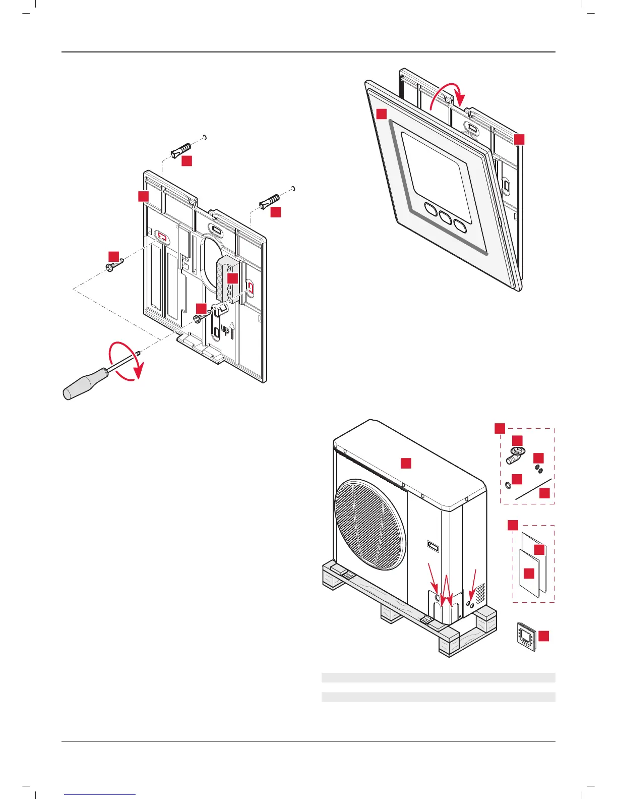
9 Installing the heat pump
9.1 Scope of delivery
1
3
4
2
2.1
2.2
2.4
2.3
2.2
2.4
2.3
3.1
3.2
Key
1 Heat pump (x1)
2 Packet of accessories (x1)
2.1 Condensate connection (x1)
2.2 Leak-tight seal for passing mains and low-voltage
cables
(x2)
INSTALLATION
 Loading...