0020117819_01 - 05/11 - Glow-worm
- 24 -
ʎPP
ʎPP
ʎPP
ʎPP
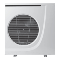
• Attach the electrical cables using the cable pass-through
located in the electrical box in order to ensure good resistance
to pulling (for the 14kW model, use the anti-wrench connector
supplied with the appliance).
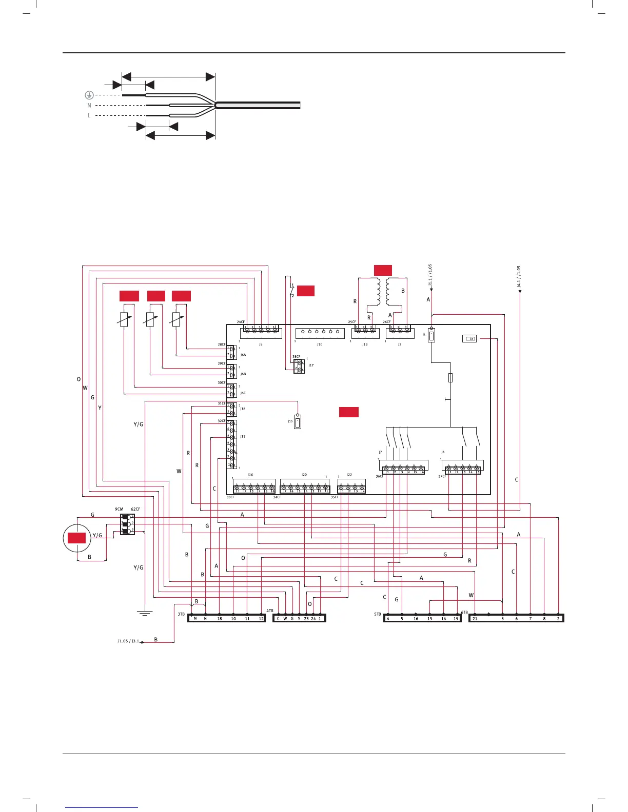
13.5 Wiring diagram
13.5.1 Command board 7kW, 12kW, 14kW
1FS
1T
1TR
1PS
1LWT 1EWT
1PCB
Key
1PS Circulator
1LWT Flow temperature sensor for heat pump circuit
1TR Temperature sensor for detecting the end of defrost
1EWT Temperature sensor for fl ow of heat pump circuit
1FS Flow detector
1T Transformer
1PCB Command board
INSTALLATION
 Loading...