0020117819_01 - 05/11 - Glow-worm
- 6 -
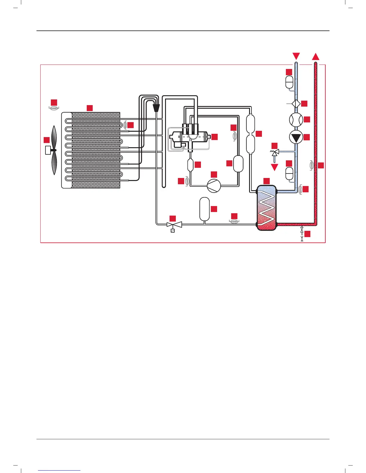
2.5 Hydraulic and refrigerant schematic
9
10
11
12
14
15
16
17
19
20
22
23
21
18
24
1
3
2
4
5
6
7
A
C
13
8
B
Key
1 Fan (1 fan for the 7 kW model, 2 fans for the 12 and 14 kW models)
2 Outside air temperature sensor
3 Finned heat exchanger
4 Finned heat exchanger temperature sensor
5 4-way cycle inversion gate
6 Temperature sensor for compressor suction
7 Silencer
8 Expansion vessel (in this position for the 7 kW model)
9 Automatic purge vent for the heat pump circuit
10 Water fl ow detector for the heat pump circuit
11 Circulator for the heat pump circuit
12 Safety valve for the heat pump circuit
13 Expansion vessel (in this position for the 12 and 14 kW models)
14 Flow temperature sensor for the heat pump
15 Return temperature sensor for the heat pump
16 Draining valve for the heat pump circuit
17 Plate to plate exchanger
18 Pre-expansion temperature sensor
19 Anti-slugging bottle
20 Rotary compressor
21 Liquid tank
22 Silencer
23 Compressor discharge temperature sensor
24 Electronic expansion unit
A Heat pump return
B Heat pump fl ow
C Evacuation from the safety valve to a container for recovering glycol
water
INTRODUCTION
 Loading...