0020117819_01 - 05/11 - Glow-worm
- 5 -
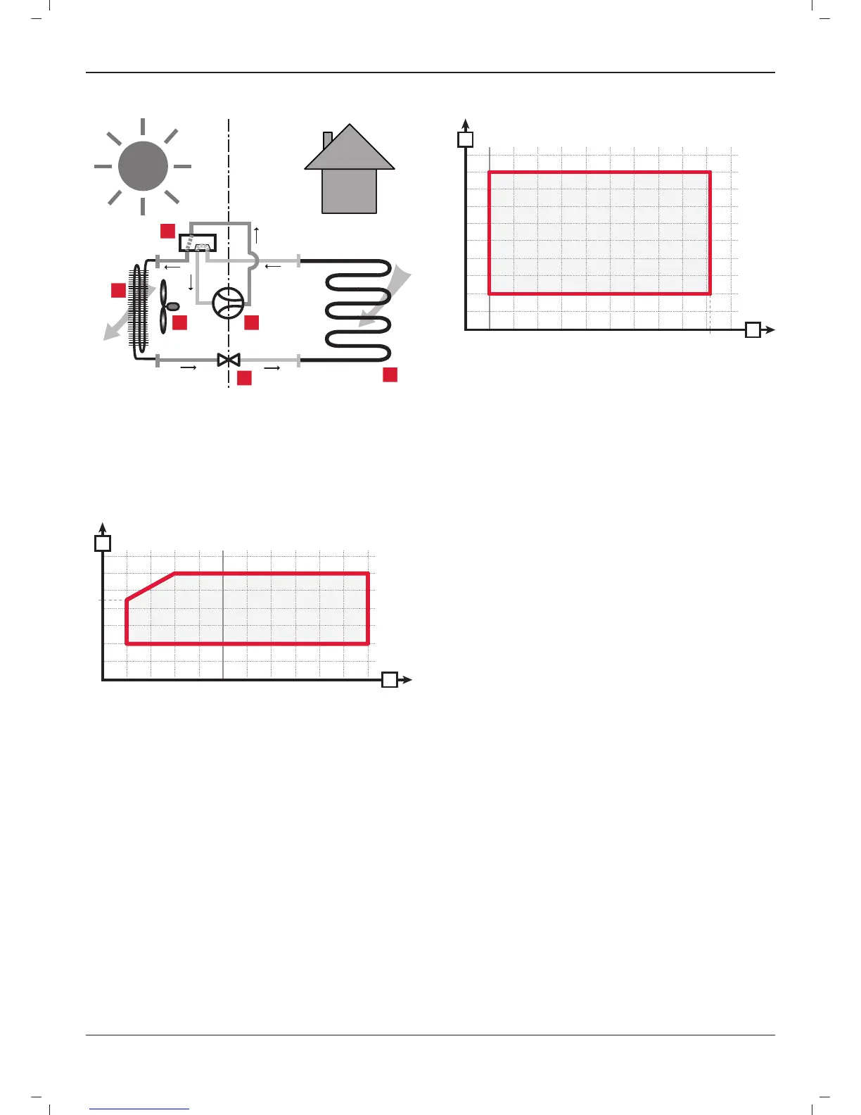
2.4.2 In defrosting and cooling mode
2
1
3 4
5
6
Key
1 Finned heat exchanger
2 Reverse cycle valve
3 Ventilating fan
4 Compressor
5 Pressure regulator
6 Exchanger with plates
2.4.3 Min. and Max. temperature settings in heating
60
50
70
40
45
30
20
10
0
-20 -10 0 10 20 30
A
B
Key
A Water temperature
B Air temperature
2.4.4 Min. and Max. temperature settings in cooling
12
14
16
18
20
10
8
6
4
2
0
01020304050
46
A
B
Key
A Water temperature
B Air temperature
2.4.5 Principle for controlling the heat pump
Control using the Glow Worm control unit. This confi guration is
recommended in the case of an installation with the Glow Worm
hydraulic unit. The Glow Worm system of active management of
the heat pump using dry 12V contacts. The command unit is used
only as a confi guration tool.
INTRODUCTION
 Loading...