0020117819_01 - 05/11 - Glow-worm
- 23 -
- weather resistant.
- equipped with wires adapted to appliance’s power rating.
• Connect the heat pump to an electrical panel via an
independent protection system (diff erential breaker with at
least 3 mm between each contact). See the table below.
Additional protection may be required during installation to
ensure buff er category II.
The power supply cut-off devices must allow complete
disconnection of the power under the conditions required for
over-voltage category III.
Description Unit 7 12 14
Electricity supply
V-ph-
Hz
230 - 1 - 50
Acceptable voltage range V 207/254
Maximum power absorbed kW 2.7 5.1 5.1
Maximum current A 14 23 20
Power fuse (gL) A 15 Type B 25 Type D 25 Type D
Maximum current in glycol
pump
A2
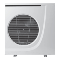
13.1 Access to main board
B
A
A
A
C
2
1
Key
1 Terminal blocks for 230 V and 12 V connection
2 Front panel
• Remove the fastening screws (A).
• Slide the front panel (2) downwards (B) and pull it towards
yourself (B) using the handle.
• To close the appliance, carry out the operations in reverse order.
13.2 Cable passage
e
The low and mains voltage cables must be inserted in
diff erent sleeves.
2
1
Key
1 Mains-voltage cable passage
2 Low-voltage cable passage
• Insert the electrical power cables in passages (1) and (2)
provided for this purpose.
• Make sure that the electrical cables are not in contact with the
compressor and the hot pipes.
• Fix the electrical cables with the clamps installed inside the
heat pump.
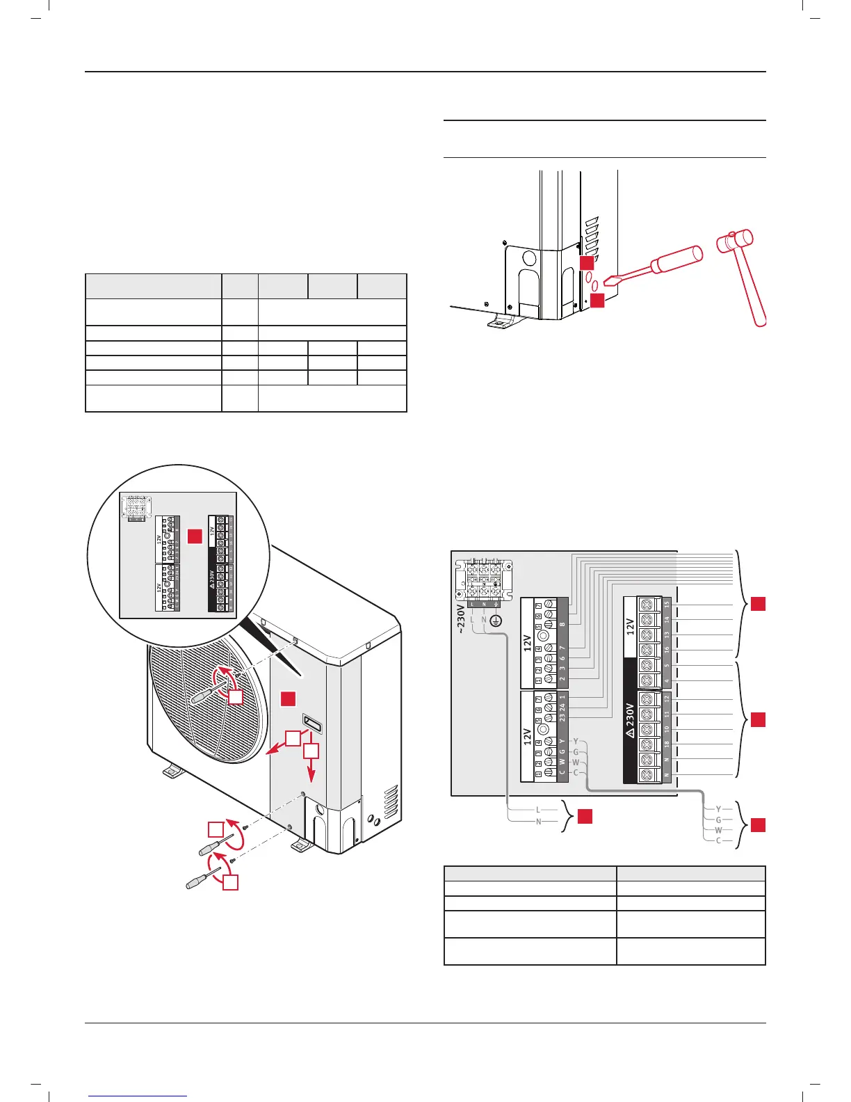
13.4 Electrical wiring
3
2
4
1
Key Recommended cable section
1 230 V power cable H07RN-F 3 x 2.5 mm²
2 12 V cable 0.75 mm²
3
230 V cable (outputs 2A
maximum)
0.75 mm²
4
Connection cable for the
command unit
4 x 0.75 mm²
INSTALLATION
 Loading...