0020117819_01 - 05/11 - Glow-worm
- 19 -
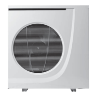
Key
1 Heat pump
2 Power supply and electrical protection for the heat pump (*)
3 Command unit for the heat pump
4 Glow Worm control unit (*)
5 Glow Worm hydraulic module (*)
6 Anti-sludge fi lter (*)
A Flow heat pump circuit
B Return heat pump circuit
E Return heating circuit
F Flow heating circuit
H Discharge from the safety valve to a container for recovering glycol
water solution
(*) Not delivered with the appliance
Adjusting the heat pump's command unit
• To fi nd out the description of each function,
see the chapter "Specifi c adjustment".
i
The setting of codes 112, 114, 117, 122, 123,
124, 125, 126 must be identical on the heat pump
command unit and the systempro control unit.
Menu Name of the function Value Factory setting
100 Type of system regulation 22
101 Confi guration of the command unit 00
112 External calibrated adjustment graphs 7 - 12 (*) 8
114 ECO heating mode 1 - 20°C (*) 5°C
117 External calibrated adjustment graphs for cooling 0 (*) 2
122 Maximum reference exterior temperature 24 - 46°C (*) 40°C
123 Exterior temperature from which the heat pump stops in cooling mode 0 - 30°C (*) 22°C
124 Minimum temperature of water in the installation in cooling mode 4 - 20°C (*) 4°C
125 Maximum temperature of water in the installation in cooling mode 4 - 20°C (*) 12°C
126 Confi gurations exterior sensor 22
146 Confi guration for stopping the heat pump if control by S1 contact input 1 2
147 Confi guration of the output between terminal channels 5 and N 1 1
148 Limit exterior temperature (T0) -20°C -20°C
155 Functioning of main circulator 01
(*) Refer to the system installation manual for pairing the settings of these codes.
Application conditions
- Command unit used as confi guration tool (see the chapter
"Location of the appliance"),
- Installation with underfl oor heating (< 53°C) or low-
temperature radiator (<60°C),
i
For the dimensioning of the cables and the electrical
protection on the appliances, see the chapter
"Electrical connection".
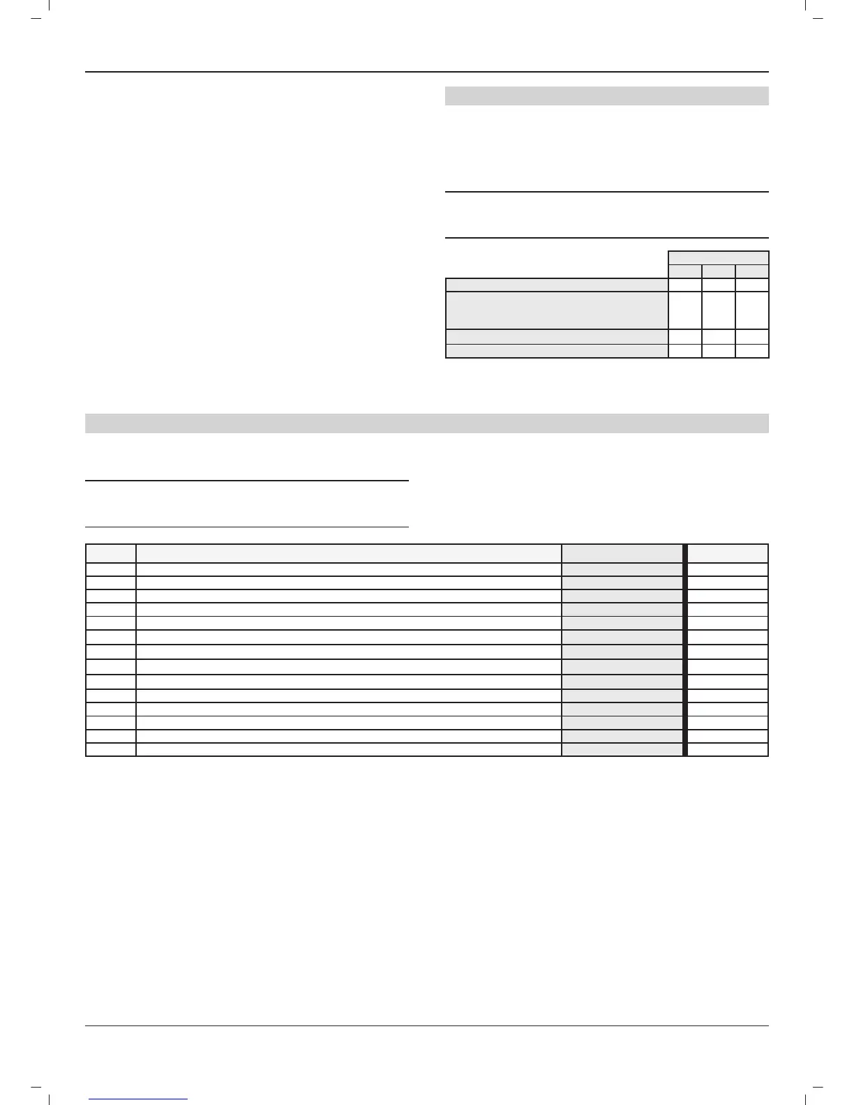
Envirosorb
71214
Minimum volume of the installation (l) 28 42 49
Max volume of heat pump circuit, without
additional vessel, for a water outlet temperature
of 35°C (l)
65 95 95
Volume of water in the heat pump
1.2 2.3 2.3
Nominal water fl ow rate (m³/h) 1.2 2.1 2.5
INSTALLATION
 Loading...