23
10.2 Horizontal Telescopic Flue - A2043600
Refer to diagram 10.2 for kit contents.
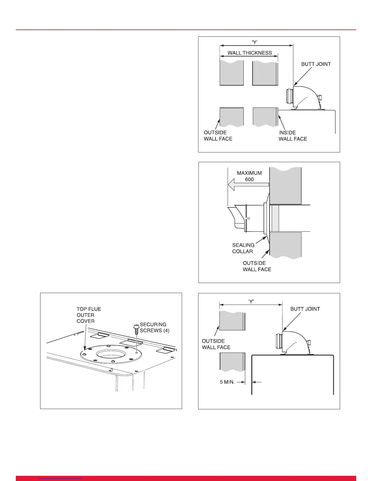
10.3 REAR Flue
If a wall thickness is between 231mm min. to 441mm max.
then the ue can be used without extensions.
Remove the top ue outlet cover secured with four screws,
see diagram 10.4.
Using these screws inserted into the same holes on the boiler,
temporarily secure the ue elbow, measure the distance
from the outside wall to the butt joint, see diagram 10.5. If
the measurement ‘Y’ exceeds 525mm, then the appropriate
length of extension pipe is required.
If the dimension is less than 315mm DO NOT cut the ue, it
can project to a maximum of 600mm, refer to diagram 10.6. If
this is not desirable then a Standard ue MUST be used and
cut to length.
10.4 SIDE Flue
Remove the top ue outlet cover secured with four screws,
see diagram 10.4.
Using these screws inserted into the same holes on the boiler,
temporarily secure the ue elbow, measure the distance
from the outside wall to the butt joint, see diagram 10.7. If
the measurement ‘Y’ exceeds 525mm, then the appropriate
length of extension pipe is required.
If the dimension is less than 315mm DO NOT cut the ue, it
can project to a maximum of 600mm, refer to diagram 10.6. If
this is not desirable then a Standard ue MUST be used and
cut to length.
Diagram 10.5
13223
Diagram 10.6
12979
10 Telescopic Flue - Length, Preparation and Installation
Diagram 10.7
13224
Diagram 10.4
13016

 Loading...


