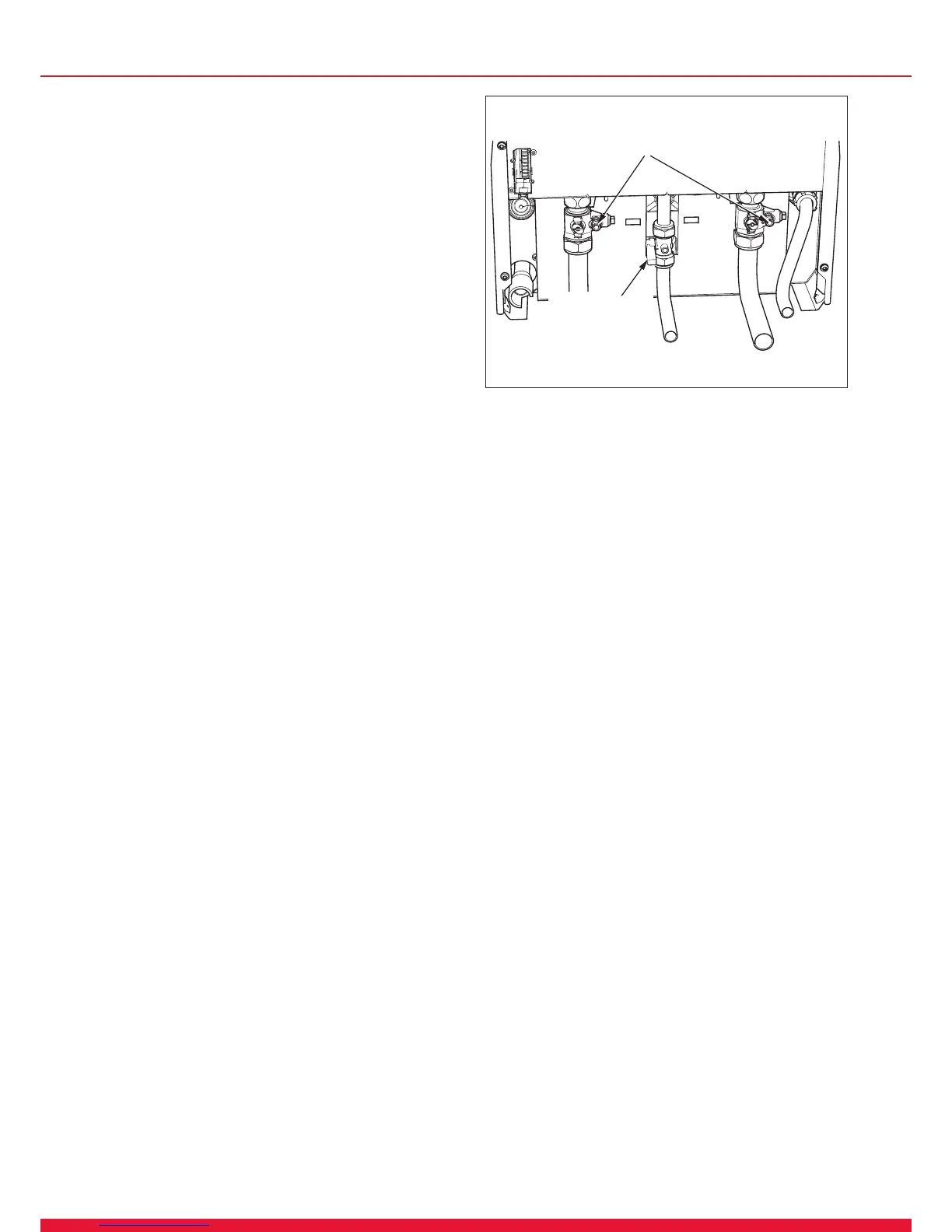
GAS SERVICE
ISOLATION
VALVE
15 Replacement of Parts
15.1 General
Replacement of parts must be carried out by a competent
person approved at the time by the Health and Safety
Executive.
Before replacing any parts the boiler should be isolated from
the mains electric supply and the gas should be turned off
at the gas service isolation valve on the boiler, see diagram
15.1.
Ensure that components with electrical connections are
disconnected before removal.
Unless stated otherwise parts are replaced in the reverse
order to removal.
After replacing any parts always test for gas soundness and if
necessary carry out functional test of the controls.
For replacement of parts the front casing of the boiler will
need to be removed. To remove undo the two screws on the
underside of the front casing and lift off.
15.2 Draining of Boiler Heating Circuit
Drain down the Heating Circuit of the boiler only, by closing
the heating ow and return isolating valves on the wall
mounting jig.
Attach a length of hose to the drain point and open the drain
valve, see diagram 15.1.
Check for leaks.
15.3 Igniter Unit
For access, refer to section 15.1.
Remove ignition lead and electrical connections then remove
igniter unit by removing two securing screws, see diagram
13.8.
15.4 Ignition Lead
For access, refer to section 15.1.
Pull the spark plug style connector off the spark electrode
and the spade connector connected to the igniter unit, see
diagrams 13.5 and 13.8.
15.5 Silencer Assembly (front)
For access, refer to section 15.1.
Pull forwards to remove.
The silencer is a push t so no tools or xings are required for
its removal or tting, see diagram 13.7.
Diagram 15.1
13046

 Loading...


