8
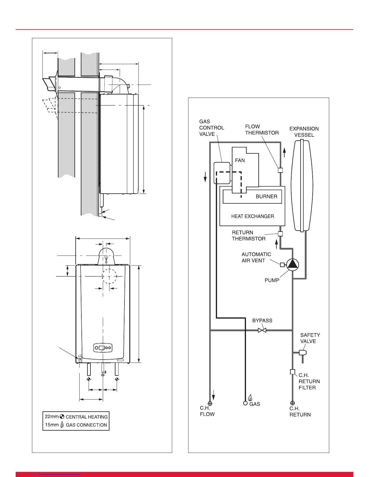
2 Boiler Dimensions and Hydraulic Schematic
Diagram 2.1
2.1 Boiler Dimensions and Hydraulic
Schematic
All dimensions are given in millimetres (except as noted).
The general arrangement of the boiler is shown in diagram
2.1. and the hydraulic and gas schematic, diagram 2.2.
The data label is positioned on the front of the inner casing
panel.
13899
167.5
100
100
700
390
280
149
C
L
FLUE
C
L
FLUE
C
L
FLUE
C
L
FLUE
 Loading...


