15
221691B
7 Commissioning
Please ensure the “Benchmark” logbook is completed and left
with the user.
7.1 Commissioning and Testing the Boiler
The whole of the system should be thoroughly flushed out with
cold water with the pump removed. Make sure that all valves
are open. Refit the pump and fill the system. Examine for water
soundness and vent all air from the system, including the pump.
CAUTION: The following work should be carried out by a
competent person.
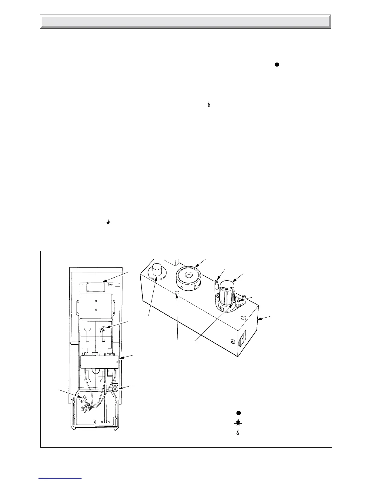
Identify the boiler controls by reference to diagram 7.1.
Check that the gas service tap “K” is closed, indicator line
horizontal.
Open all windows and put out any naked lights, pipes or
cigarettes.
Purge air from the gas supply in accordance with the current
issue of BS6891.
Make sure that the thermostat phial is positioned at the bottom
of the phial pocket “J” located by the washer being behind the
split pin.
See that the mains electrical supply is switched off.
Set thermostat control knob “B” to “O”.
Remove gas pressure test nipple screw “G” and fit a suitable
pressure gauge.
Open gas service cock “K”.
Turn gas control knob “A” to
ignition and pilot position and
push in. At the same time push and release piezo unit button
“C” until the pilot burner lights. At this stage air may be present
in the gas pipes and the lighting operation may need repeating.
Diagram 7.1
BOILER COMPONENTS
0940
A GAS CONTROL KNOB J PHIAL POCKET
B TERMOSTAT CONTROL K GAS SERVICE COCK
C PIEZO IGNITION BUTTON L DATA LABEL
E VIEWING WINDOW
F BURNER GAS RATE GAS CONTROL KNOB 'A'
ADJUSTMENT POSITIONS:-
G BURNER PRESSURE
TEST POINT
H CONTROL BOX
= OFF
= PILOT/IGNITION
= MAIN BURNER
C
H
K
(Shown
closed)
SETTING
POINTS
B
G
A
F
H
L
J
E
When the pilot is alight, keep control button “A” fully pushed in
for about 15 seconds. If the pilot burner fails to stay alight,
repeat the lighting procedure but now keep the control button
pushed in for a little longer.
If the gas control knob “A” is turned to
, a safety lock prevents
it being turned on again. No attempt should be made to push
in knob “A” until 3 minutes have gone by.
Make sure that the pilot burner is alight and stable, see
diagram 7.2 for flame dimensions, then switch the electrical
supply on. Set any remote controls for duty. Turn control knob
“A” to
main burner position. Set thermostat control knob “B”
between “MIN” and “MAX” opposite the setting point on the
control box, the main burner will then light, “MAX” is about 82
o
C
(180
o
F).
Test for gas soundness around the boiler with a suitable leak
detection fluid.
Set the burner gas rate required ten minutes from lighting, see
page 2 for settings. Adjust screw “F”, diagram 7.1 to obtain the
required heat input. Turn anti-clockwise to increase.The adjusting
screw should then be sealed.
Should there be any doubt about the gas rate it should be
checked at the meter.
This should be in the range of:
Hideaway 40B : 1.1 to 1.4m
3
/h 38 to 50ft
3
/h
These rates are for guide purposes, depending on the heat
setting.
Stick the self adhesive arrow indicator onto the data label
against the output the boiler is to be set to, the arrow is in the
fittings pack.
 Loading...


