5
221899A
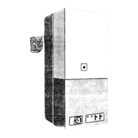
FRONT
VIEW
2mm
2mm
*
6mm
10mm FROM A NON-PERMANENT
300mm FROM A PERMANENT
6mm
6mm
50mm
Diagram 1.3
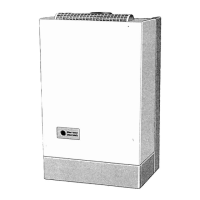
1.12 Boiler Clearances
Refer to diagram 1.3.
This boiler must be positioned so that at least the minimum
operational and servicing clearances are provided.
Additional clearances may be required for installation.
If fixtures are positioned next to the boiler ensure access is
provided for pipework installation.
At least a minimum clearance of 300mm from a permanently
fixed surface must be left in front of the boiler for servicing, see
diagram 1.3.
1.13 Room Ventilation
The boiler is room sealed and does not require the room or
space containing it to have permanent air vents.
7064
1 General
Alternatively, an unswitched shuttered socket outlet and 3A
fused 3 pin plug, both to the current issue of BS1363 may be
used provided that they are not used in a room containing a bath
or shower.
Wiring to the boiler must be PVC 85
0
C insulated cable, not less
than 0.75mm
2
(24/0.20mm).
1.7 Contents of Packaging
The boiler is delivered in one pack with the flue system packed
separately.
1.8 Water System
This boiler may be fitted to an open vented or a sealed water
system.
1.9 Draining Tap
System
A draining tap must be provided at the lowest points of the
system which will allow the entire system and hot water cylinder
to be drained.
Draining taps should be to the current issue of BS2879.
Boiler
A draining point is fitted at the bottom right hand side of the heat
exchanger.
When draining is required cover the controls to avoid water
damage.
If required remove the combustion chamber front cover to
improve access.
1.10 Safety Valve
A safety valve need not be fitted to an open vented system.
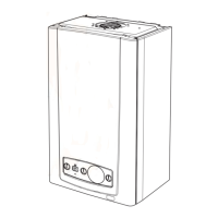
1.11 Location
This boiler is not suitable for outdoor installation.
This boiler may be installed in any room, although particular
attention is drawn to the requirements of the current issue of
BS7671 with respect to the installation of a boiler in a room
containing a bath or shower. Any electrical switch or boiler
control utilising mains electricity should be placed so that it
cannot be touched by a person using the bath or shower.
The electrical provisions of the Building Standards (Scotland)
apply to such installations in Scotland.
The boiler must be mounted on a flat wall which is sufficiently
robust to take its total weight.
The boiler may be fitted to a wall made of combustible material.
Diagram 1.2
7262
HEPWORTH HEATING LTD.,
BELPER,DERBYS. DE56 1JT
MICRON 40FF
458111
SERIAL No.
GC No. 41-047-17
0086
86/AU/000
GB IE
230V 50Hz 66W Fused at 3A
For use on G20 gas only
Supply pressure 20 mbar
This boiler is intended exclusively
to be installed on a gas supply
with a governed meter
~
RANGE RATING MIN MID MAX
HEAT
INPUT NETT
kW
kW
Btu/h
Btu/h
HEAT
OUTPUT
HOT BURNER
PRESSURE
mbar
in wg
5.7
14.3
40000
44493
13.04
11.50
4.4
11.0
35000
10.26
39222
9.95
3.1
7.8
30000
8.79
33957
11.72
INJECTOR: 3.0mm 205757
Cat.
EN437
I
2H
TYPE C C
PMS
=
3.0 bar
Q =
P =
NO Class 2
x
32,12,
C
52
PMS = 3.0 bar, is: Maximum water-side operating pressure.
The appliance flue type is a C
12
, C
32
and C
52
. This refers to a
concentric or twin flue where the fan is downstream of the heat
exchanger. The C
12
is a horizontal flue termination, the C
32
is a
vertical flue termination and the C
52
has seperate ducts to two
terminals that may terminate in zones of different pressure.
DATA
LABEL
7316
190mm with Easyfit top flue fitted,
160mm with standard/extended top flue fitted,
20mm without top flue fitted
Increased top clearance is required if flow pipe enters from
below to permit access to air vent.
MINIMUM CLEARANCES FROM WALLS, CEILING, FLOOR,
CUPBOARD, WORKTOPS AND INFLAMMABLE MATERIALS
*
*