6
221899A
1.14 Boilers in a Compartment
Where the installation of the boiler will be in an unusual position,
the current issue of BS6798 gives detailed guidance on these
requirements.
An existing cupboard or compartment modified for the purpose
may be used, providing minimum clearances are maintained.
Details of essential requirements for cupboard or compartment
design are given in the current issue of BS6798.
The doorway opening should be of sufficient size to allow for easy
removal of the boiler.
Where the boiler is fitted in a cupboard or compartment, permanent
ventilation is not required.
1.15 Timber Frame Building
IIf the boiler is to be installed in a timber frame building it should
be fitted in accordance with the Institute of Gas Engineers
document IGE/UP/7/1998. If in doubt seek advice from the local
gas undertaking or Hepworth Heating Ltd.
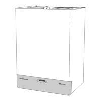
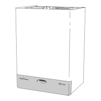
TABLE 1.
TOTAL DRY WEIGHT
(Including Terminal)
LIFT WEIGHT
WATER CONTENT
GAS CONNECTION
ELECTRICITY RATING
WATER CONNECTION
ELECTRICITY SUPPLY
DATA LABEL
36.4 kg (80lb)
29.7 kg (65.34lb)
2.2 litre (0.48 gallon)
Rc
1
/
2
in.
66W Internal fuse Type F4A
2x22mm copper pipes from
back of case
230V~50Hz,fused 3A
Top left hand inside of case
The flue must be installed in accordance with the rules in force
in the countries of destination.
2.1 Terminal Position
The minimum acceptable siting dimensions for the terminal
from obstructions, other terminals and ventilation openings are
shown in diagram 2.1.
The terminal must be exposed to the external air, the position
allowing free passage of air across it at all times.
Car ports or similar extensions of a roof only, or a roof and one
wall, require special consideration with respect to any openings,
doors, vents or windows under the roof. Care is required to
protect the roof if it is made of plastic sheeting. If the car port
consists of a roof and two or more walls, seek advice from the
local gas company before installing the boiler.
If the terminal is fitted within 600mm below plastic guttering or
painted soffit an aluminium shield 1500mm long should be fitted
immediately beneath the guttering or eaves. If the terminal is
fitted within 450mm below painted eaves or a painted gutter, an
aluminium shield 750mm long should be fitted immediately
beneath the guttering or eaves.
2.2 Flue Options
There are various flue systems to choose from, as follows:
Standard Top Outlet Flue Pack - Pt.No. 230483
Easyfit Top Outlet Flue Pack - Pt. No. 232057
Standard Rear Outlet Flue Pack - Pt. No. 230482
Extended Top Outlet Flue Pack - Pt. No. 230487
1 Metre Extension Kit - Pt. No. 230484
A flue system up to 3 metres in length can be made by
connecting 1 metre flue extension kits together.
Optional Wall Liner Kit No. 900862
A Flue Bend Kit or Vertical Flue Kit up to 4 metres can be
supplied, see Hepworth Heating "Flue Options Guide" for
configurations available.
45
o
Flue Bend Pack - Pt. No. 230485
90
o
Flue Bend Pack - Pt. No. 230486
In Line Flue Adapter Kit - Pt. No. 230488
Vertical Flue Kit No. 458115
1 General
2 Flue and Ventilation
Diagram 2.1
0103M
A
A
F
G
E
A
G
G
G
B,C
B,C
F
F
K
K
K
C
G
L
L
Under Car Port etc.
H,I
J
D
F
K
M
MINIMUM SITING DIMENSIONS FOR
FANNED FLUE TERMINALS POSITION
A DIRECTLY BELOW, ABOVE OR HORIZONTALLY
TO AN OPENING, AIR BRICK, OPENING
WINDOWS, AIR VENT OR ANY OTHER
VENTILATION OPENING. 300
B BELOW GUTTER, DRAIN/SOIL PIPE 25
C BELOW EAVES 25
D BELOW A BALCONY OR CAR PORT 25
E FROM VERTICAL DRAIN PIPES AND SOIL PIPES 25
F FROM EXTERNAL CORNERS 25
G ABOVE ADJACENT GROUND OR BALCONY LEVEL 300
H FROM A SURFACE FACING THE TERMINAL 600
I FACING TERMINALS 1200
J FROM OPENING (DOOR/WINDOW) IN
CAR PORT INTO DWELLING 1200
K VERTICAL FROM A TERMINAL 1500
L HORIZONTALLY FROM A TERMINAL 300
M FROM INTERNAL CORNERS 25
MINIMUM
SPACING in mm
1.16 Anti-theft Kits
Anti-theft kits are available for these appliances, contact
Hepworth Heating Ltd. for further information.

 Loading...