Do you have a question about the Glow-worm Micron 80FF and is the answer not in the manual?
| Mounting | Wall Mounted |
|---|---|
| Output | 24 kW |
| Fuel Type | Natural Gas |
| Weight | 31 kg |
| Flow Rate (l/min) | 9.8 l/min |
| Central Heating Flow Temperature Range | 30 - 80°C |
| Hot Water Flow Rate at 35°C Rise | 9.8 l/min |
Information on registering your Glow-worm appliance for its first year guarantee protection.
Details on boiler testing, certification, and compliance with safety and performance standards.
Explanation of the CE mark and its compliance with EU directives on efficiency and safety.
Information regarding substances hazardous to health, specifically insulation pads and glass yarn.
Guidance on using only approved spare parts to maintain safety and performance.
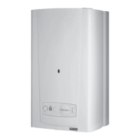
Read these instructions for safe and economical boiler use. Boiler is fully automatic with one user control.
Immediate actions to take in case of a gas leak or fault, including shutting off gas and ventilating.
Procedure to follow if the electrical supply fails, including boiler restart and safety cutoff reset.
Actions to take if the safety temperature limiter operates, including checking for overheating.
Measures to prevent freezing during periods of disuse, including system draining and frost protection features.
Recommendation for regular checks and servicing to ensure continued efficient and safe operation.
Instructions for cleaning the boiler casing safely, avoiding abrasive cleaners.
Step-by-step guide on how to turn the boiler on, including pressure checks and control knob operation.
Guidance on turning the boiler off for short or long periods.
Information on using an optional programmer for automatic on/off switching of the heating system.
Boiler is for Natural Gas (G20) only, must be installed by a competent person, and can be used on vented or sealed systems.
User must not interfere with or adjust sealed parts.
Warning about handling sheet metal parts to avoid personal injury.
Details of UK and IE regulations and codes of practice for boiler installation.
Information on SEDBUK rating, SAP use, and test data certification by B.S.I.
Boiler can be range rated to suit system requirements; refer to data label for settings.
Requirements for gas installation in GB and IE, including pressure and soundness testing.
Guidelines for electrical supply connection, earthing, polarity, and cable types.
Information on the boiler packaging contents, which may vary depending on flue system.
Notes that the boiler may be fitted to an open vented or sealed water system.
Details on system and boiler draining points and precautions during draining.
Note on safety valve requirements for open vented systems.
Guidance on suitable installation locations, including bathroom zones and electrical safety considerations.
Minimum operational and servicing clearances required around the boiler for safe installation and maintenance.
Information that the boiler is room sealed and does not require additional room air vents.
Requirements for installing boilers in cupboards or compartments, including minimum clearances.
Guidance for installing boilers in timber frame buildings, referencing IGE/UP/7/1998.
Information about the availability of anti-theft kits for the appliance.
Minimum siting dimensions for the terminal from obstructions, referencing UK and IE regulations.
Details of available flue systems, extension kits, and bend kits for installation.
Requirements for installing a terminal guard if persons could come into contact with the terminal.
Built-in frost stat functionality and system vulnerability considerations.
Guidance on pump fitting, setting temperature difference, and microbore systems.
Information on when a bypass is required and its connection, especially with TRVs.
Requirements for open vented systems, including supply and cistern fitting.
General requirements for domestic hot water circuits and fittings, referencing standards.
Recommendations for indirect hot water cylinders and temperature control.
Connection requirements for open vented systems as shown in diagrams.
Attention to BS5449 and BS7593 on inhibitor use and system cleaning.
Installation compliance with relevant British Standards for sealed water systems.
Requirements for safety valve fitting in sealed systems, including pressure and connections.
Guidance on diaphragm expansion vessel selection and sizing for sealed systems.
Requirement for a permanently fitted pressure gauge in sealed systems.
Suitability of indirect coil cylinders and pressure requirements for domestic hot water.
Compliance with regulations for unvented storage systems and local authority advice.
Provision for system filling at low level and compliance with BS5449.
Provision for replacing water lost from the system using a make-up vessel.
Details on flue length calculations and clearances for top outlet flue packs.
Description of rear outlet flue packs and their assembly with extension kits.
Guidance on joining extension kits and maximum flue system lengths.
Table showing maximum distances for flue packs from boiler mounting face and casing.
Determining flue application, length, and terminal position, including instructions for kits.
Information on internal and external flue installation, including wall liner kit use.
Selecting boiler location and flue application, with template use for marking.
Instructions for cutting the flue hole, including drill size and optional wall liner kit.
Steps for positioning the template, marking fixing points, and securing the mounting bracket.
Extending telescopic flue, ensuring overlap, and terminal projection beyond wall face.
Instructions for flue system installation from inside using an optional wall liner kit.
Steps for fitting flue duct extension, fan elbow, and securing the assembly for rear flue.
Procedure for fitting flue duct extension and fan elbow for top or side flue arrangements.
Guidance on pushing the flue assembly into the hole and securing it to the boiler.
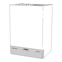
Instructions for unpacking the boiler and checking items against the pack contents list.
Steps to prepare the boiler, including removing casing, opening controls cover, and fitting tail pipes.
Procedure for fitting blanking plates, flue spigots, and securely mounting the boiler to the wall.
Detailed steps for fitting the fan elbow, retaining clamp, and securing the flue duct for rear flue connections.
Instructions for fitting 'O' rings, air deflector, flue duct extension, and fan elbow for top flue.
Steps for completing water connections, filling, venting, flushing, and checking for leaks.
Requirements for gas connection, including testing for soundness and purging.
Procedure for accessing the control box by loosening the securing screw and swinging it open.
Detailed instructions for making electrical connections, including earthing and cable types.
Routing the pump cable and connecting it to the control box terminal block.
Checks to ensure electrical safety, carried out by a competent person.
Commissioning procedures for all systems, including water flushing, pump refitting, and air venting.
Specific commissioning steps for sealed systems, including pressure checks and safety valve testing.
Procedure for initial boiler lighting, testing controls, gas soundness, and electrical safety.
Detailed electrical testing procedures, including lighting sequence and safety checks.
Gas soundness testing, main burner gas pressure checks, and gas rate measurement.
Checking for water leaks at maximum temperature and system draining/refilling.
Adjusting pump settings and balancing the system for optimal performance.
Considerations for systems with TRVs, including bypass requirements and temperature differences.
Final steps including setting controls, completing logbook, and flue gas testing.
Instructing the user on safe and efficient operation, system checks, and servicing recommendations.
Highlighting user duties regarding property letting, sealed components, and competent person servicing.
Advising the user on precautions to prevent system damage from freezing conditions.
Procedure for obtaining products of combustion readings using an analyser.
Steps to gain access to the boiler components for servicing.
Instructions for removing, cleaning, and refitting the burner and baffle support.
Steps for cleaning the heat exchanger flueways, including removing baffles and debris.
Inspection and cleaning of the injector manifold, including advice on injector removal and refitting.
Checks to be performed after service before refitting the case, including case seal and flue examination.
Importance of repeating electrical checks after service/fault finding, referring to various diagrams.
Actions to take for burner failure due to electrical supply issues, including reset procedures.
Troubleshooting the timed pump overrun facility and checks required before using fault finding charts.
Ensuring gas, electricity, and water availability and checking external controls before starting fault finding.
Step-by-step fault finding process for ignition and burner issues, including LED indications.
Table detailing LED status and corresponding fault conditions for troubleshooting.
General notes on safety, isolation, gas soundness testing, and functional checks before and after part replacement.
Detailed steps for accessing and replacing the electrical thermistor, including disconnection and refitting.
Procedure for accessing and replacing the safety temperature limiter device.
Steps for accessing and replacing the control board (PCB), including disconnection and refitting.
Procedure for removing and refitting the electrode, including checking the spark gap.
Instructions for accessing and replacing the multifunctional control, including gas connection.
Guidance on removing and replacing combustion chamber front, side, and rear insulation.
Steps for removing and replacing the air pressure switch, including tubes and connections.
Procedure for removing and refitting the fan assembly, including electrical connections and air tubes.
Diagram and list to help identify specific spare parts by part number and location.
Information required when ordering spare parts, including part number, description, model, serial, and GC number.