36
221469B
START
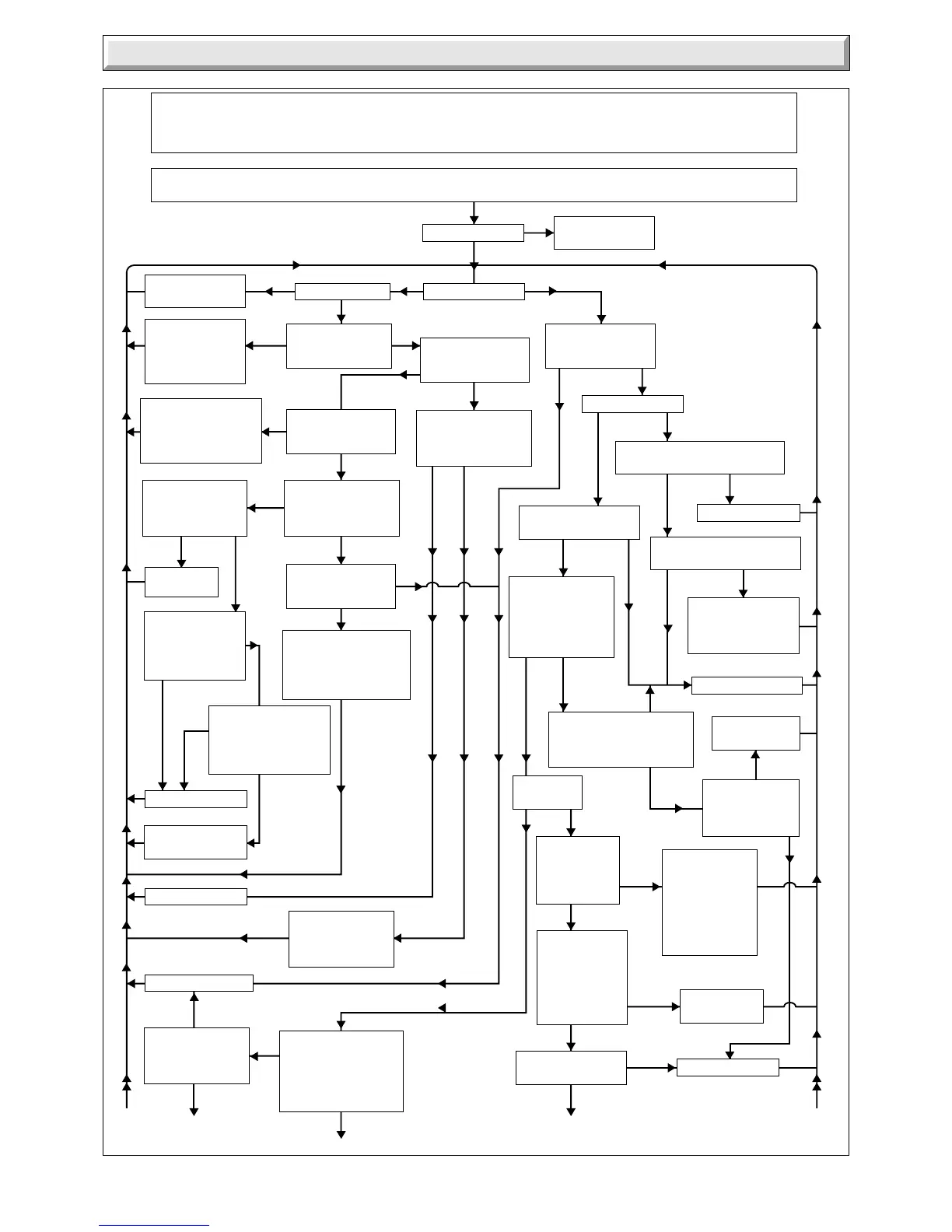
Carry out the initial fault finding checks described in section 3.1 and 3.4. Check that gas, water and electricity are available at the boiler.
There must be no external voltage applied to the control board via the central heating controls to the P.C.B. Before commencement of test,
isolate the boiler from the electricity supply, ensure that the remote controls are not calling for duty (no red link in plug and socket).
Refer to the functional flow diagrams in conjunction with the following fault finding.
Remove the outer case, control housing and its cover. Check all connections on the control board and the boiler components, rectify or
renew as necessary. A dummy two-way connector is provided for ease of testing continuity, a spare fuse is also provided.
Can pilot be lit
Does pump run?Does boiler light?
Faulty flowswitch,
replace.
Refer to pilot fault
finding
Is there 240V AC
across 'pump' pins
on block 2 on P.C.B?
Is there 240V AC
across L & N pins on
block 3 on P.C.B.?
After approx 30
seconds. Does pump
stop?
Isolate supply. Is
there continuity across
fuse FSI on P.C.B.?
Isolate supply. Is
there continuity across
fuse FS 2 on P.C.B.?
Restore supply. Is there
24V AC across 'TXR'
24V AC pins on block
1 on P.C.B.?
Increase D.H.W. flow to
11.4 litres/minute. Is
burner pressure constant
at approx :
S.I.T. 15.7mbar?
Honeywell 16.1mbar?
Isolate supply, check
continuity between
supply and P.C.B.
via plug and socket.
Rectify if necessary.
Check P.C.B.connections
and external wiring for
shorting to E or N
rectify if necessary,
replace fuse.
Remove terminal cover
from pump. Is there
240V AC across L and
N terminals on pump?
Is there between 15
and 30 V DC across
'modulator' pins on
block 1 on P.C.B.?
Isolate supply. Is
there continuity
between P.C.B. and
transformer primary
winding?
Is there 240V AC
across TXR 240V AC
pins on block 2 on
P.C.B.?
Faulty P.C.B., replace.
Faulty pump, replace.
Rectify as necessary.
Faulty P.C.B.
replace.
Faulty transformer,
replace.
Isolate supply. Check
continuity between
P.C.B. and pump.
Rectify if necessary.
Disconnect block 1 from
P.C.B. Is there continuity
between TXR 24V pins
on block 1 secondary
pins 6&7 on transformer?
Check P.C.B. connections
and wiring external to
control box for shorting to
E and N. Rectify if
necessary replace fuse.
Does Fan run?
Is there 240V AC across L and N
terminals of fan?
Faulty fan, replace.
Rectify as necessary.
Are D.H.W. thermistor
connections sound?
Isolate supply.
Remove electrical
connectors from
pressure switch.
Is there continuity
across switch
terminals?
Faulty pressure
switch. Replace.
Isolate supply.
Check heating
system for leaks.
Rectify if
necessary. Refill
& vent ensuring
automatic air vent
cap is open.
Check system
pressure. Is
there a minimum
pressure of
0.6 bar?
Does main
burner light?
Is there continuity
between P.C.B.
and flowswitch in
line connectors?
Isolate supply. Disconnect
block 4 from P.C.B. Is there
continuity across flowswitch
pins on block 4?
After approx 30 seconds
does fan speed reduce?
Is there 240V AC across 'fan'
pins on block 2 on P.C.B.?
Faulty flowswitch
replace.
Faulty P.C.B., replace.
Isolate supply. Check
continuity between
fan and P.C.B. Rectify
if necessary.
Set selector switch
to "on". With D.H.W.
flow rate of at least
4 litres/minute. Does
fan speed increase
to maximum?
NO
NO
YES
NO
NO
NO
YES
YES
YES
NO
NO
NO
NO
YES
NO
YES
NO
YES
NO
YES
YES
NO
YES
NO
YES
YES
NO
YES
NO
YES
NO
YES
NOYES
YES
NO
YES
NO
NO
NOYES
YES
NO
YES
NO YES
Continued
Continued
Continued
YES
YES NO
YES
NO
3 Fault Finding
Diagram 3.7
4490
 Loading...


