50
221469B
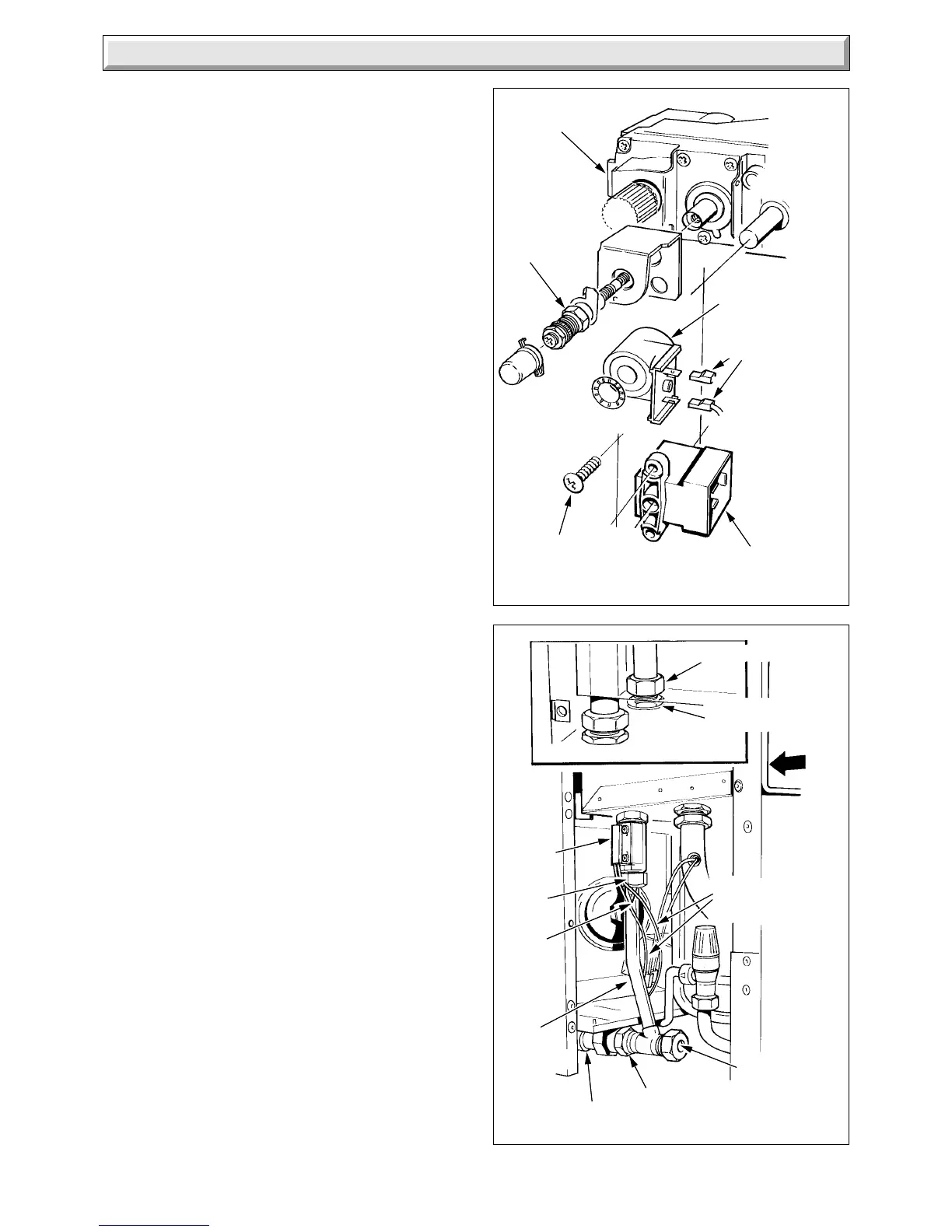
Diagram 4.14
2856 S
UNION NUT
FLOW SWITCH
LOCKNUT
VIEW ON ARROW "A"
FLOW
SWITCH
FLOW SWITCH
ELECTRICAL
CABLES
FILTER
UNION
NUT
WATER
FILTER
ISOLATING
VALVE
UNION
NUT
THROTTLE
WATER
INLET
PIPE
ASSEMBLY
"A"
4 Replacement of Parts
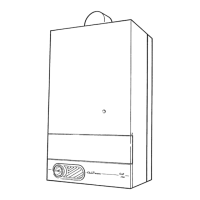
Diagram 4.13
S.I.T.
3084 S
"A"
ELECTRICAL
CONNECTORS
MODULATOR
COIL
GAS VALVE
SOLENOID
SECURING SCREW (2)
SOLENOID
4.20 Domestic Hot Water Flow Switch
Before starting refer to Section 1.1.
Isolate the boiler from the electrical supply, refer to Section 1.3.
Remove the outer case, refer to Section 1.4.
Isolate the domestic water inlet, release the domestic water
pressure and drain, refer to Section 1.3 and 1.6.
Remove the control housing, refer to Section 4.7 paragraph 7.
Remove the piezo unit bracket, see diagram 4.12.
Remove the pressure gauge bracket, see diagram 4.7.
Disconnect the flow switch cables at the in line electrical
connectors.
Remove the flow switch by disconnecting the union nuts, see
diagram 4.14, noting the fitted position. Slacken or remove the
clip securing the isolating valve to ease removal.
Discard the sealing washer and use the new ones supplied,
when fitting the flow switch. It is recommended that the water
inlet filter is cleaned or renewed at this stage. Make sure that
the switch is positioned correctly, with the flow arrow
pointing upward.
4.21 Thermistor
Before starting refer to Section 1.1.
Isolate the boiler from the electrical supply, refer to Section 1.3.
Remove the inner case, refer to Section 1.4.
Release the water pressure and drain the appropriate circuit of
the boiler, refer to Section 1.6.
Gain access, central heating thermistor only, by removing the
piezo bracket, see diagram 4.12.
Remove the control housing, refer to Section 4.7 paragraph 7.
Disconnect the cables from the appropriate thermistor
connectors, see diagram 4.15.
Remove the relevant thermistor, complete with “O” ring.
Discard the “O” ring and use the new one supplied, when fitting
the thermistor.
Make up water loss and pressurise the system, central heating
thermistor only, refer to Commissioning in the Installation
Instructions.
4.22 Safety Valve
Before starting, refer to Section 1.1.
Isolate the boiler from the electrical supply, refer to Section 1.3.
Remove the outer case, refer to Section 1.4.
Release the water pressure and drain, refer to
Section 1.6.
Remove the control housing, refer to Section 4.7 paragraph 7.
Gain access by removing the pressure gauge bracket, see
diagram 4.7.
Disconnect the pressure gauge connection from the safety
valve, see diagram 4.16.
Disconnect the union nuts to release the safety valve.
Discard the sealing washers and use the new ones supplied, on
assembly.
Make up water loss and pressurise the system, refer to
Commissioning in the Installation Instructions.
 Loading...


