51
221469B
4 Replacement of Parts
Diagram 4.15
4452 S
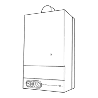
THERMISTOR
(HOT WATER)
THERMISTOR
CONNECTORS
'O' RING
THERMISTOR
(CENTRAL HEATING)
4.23 Water Inlet Filter
Before starting refer to Section 1.1.
Isolate the boiler from the electrical supply, refer to Section 1.3.
Remove the outer case, refer to Section 1.4.
Isolate domestic water inlet, release the domestic water pressure
and drain, refer to Section 1.3 and 1.6.
Remove the control housing, refer to Section 4.7 paragraph 7.
Disconnect the two union nuts to gain access to the filter, see
diagram 4.14.
Clean or renew the filter as necessary.
Discard the sealing washer and use the new one supplied, on
assembly.
4.24 Domestic Hot Water Throttle
Before starting refer to Section 1.1
Isolate the boiler from the electrical supply, refer to Section 1.3.
Remove the outer case, refer to Section 1.4.
Isolate the domestic water inlet, release the domestic water
pressure and drain, refer to Section 1.3 and 1.6.
Remove the cap nut and carefully remove the throttle adjuster,
see diagram 4.17.
Clean if necessary, taking care not to damage the throttle body.
Discard the “O” ring and use the new ones supplied, when fitting
the throttle adjuster.
4.25 Mini Expansion Vessel
Before starting, refer to Section 1.1.
Isolate the boiler from the electrical supply, refer to Section 1.3.
Diagram 4.17
2794
4600
THROTTLE
ADJUSTER
CAP
NUT
SEALING
WASHER
MINI
EXPANSION
VESSEL
Diagram 4.18
2859 S
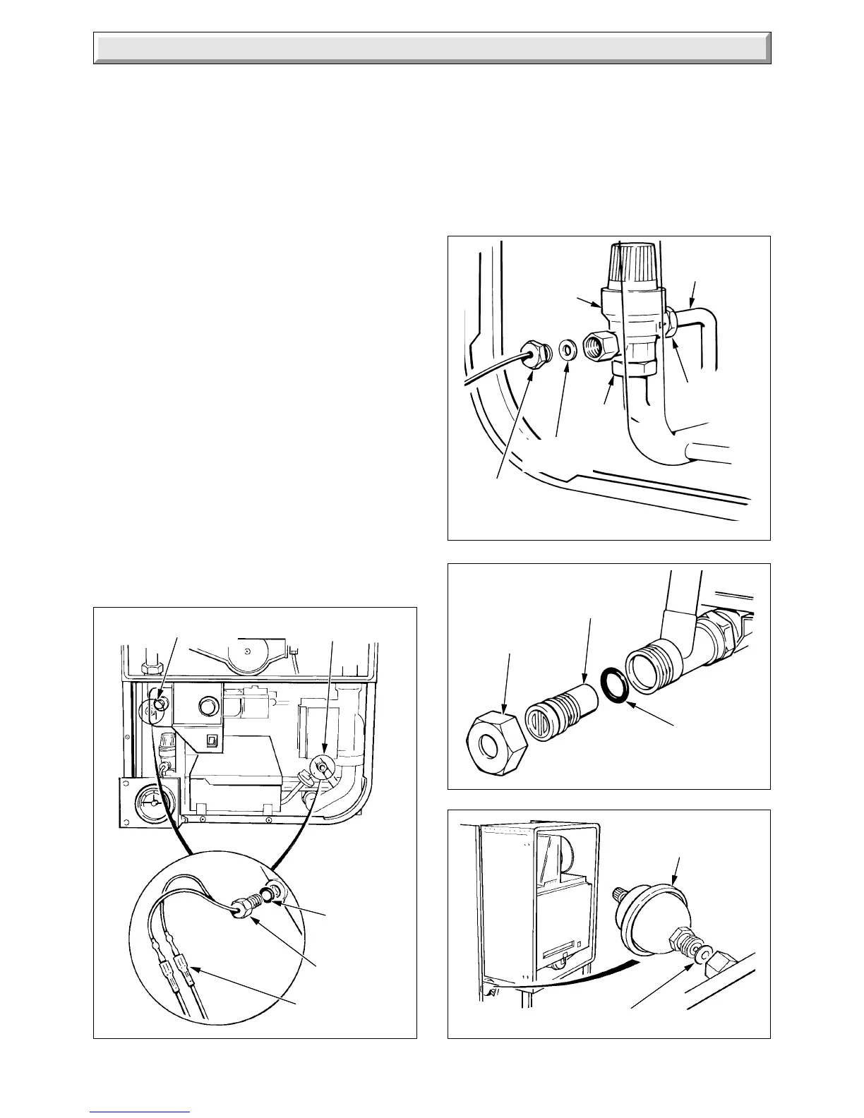
Diagram 4.16
PRESSURE
GAUGE
CONNECTION
UNION NUT
DISCHARGE
PIPE
SAFETY
VALVE
UNION
NUT
SEALING
WASHER
'O' RING
Remove the outer case, refer to Section 1.4.
Isolate domestic water inlet, release the domestic water pressure
and drain, refer to Section 1.3 and 1.6.
Remove the control housing, refer to Section 4.7 paragraph 7.
Remove the mini expansion vessel, see diagram 4.18.
Discard the sealing washer and use the new one supplied,
when fitting.
 Loading...


