52
221469B
4 Replacement of Parts
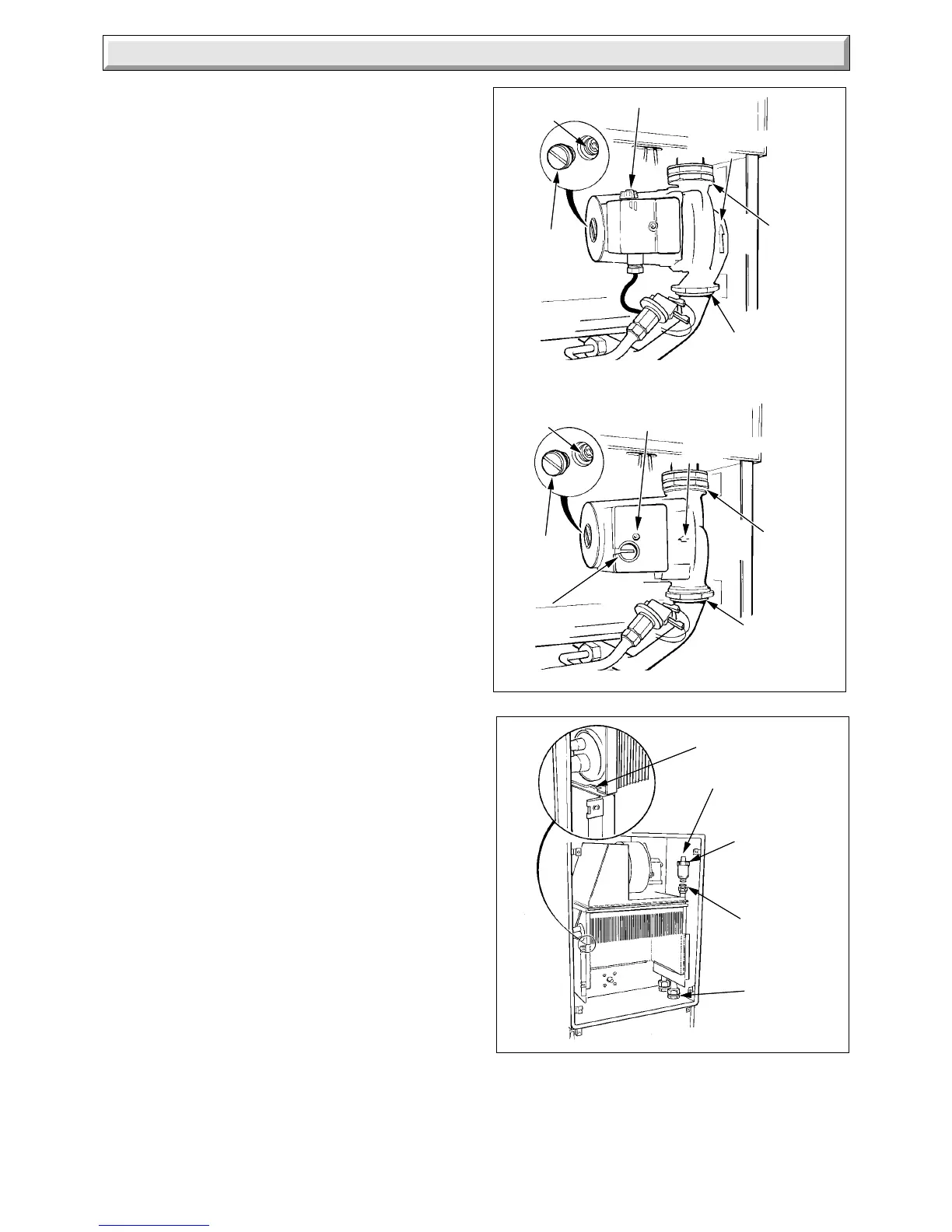
Diagram 4.20
UNION (4)
SEALING
WASHER
AUTOMATIC
AIR VENT
CAP
LOCATION
SLOT
6909
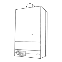
Diagram 4.19
4453 S
LOWER PUMP
UNION
END
SCREW
PUMP
SPINDLE
PUMP
ADJUSTER
UPPER
PUMP
UNION
TERMINAL
COVER SCREW
FLOW DIRECTION
ARROW
END
SCREW
PUMP
SPINDLE
UPPER
PUMP
UNION
PUMP ADJUSTER
4465
LOWER
PUMP
UNION
GRUNDFOS PUMP
WILO PUMP
FLOW DIRECTION
ARROW
4.26 Pump
Before starting refer to Section 1.1.
Isolate the boiler from the electrical supply, refer to Section 1.3.
Remove the outer case, refer to Section 1.4.
Release the water pressure and drain, refer to Section 1.6.
Remove the control housing, refer to Section 4.7 paragraph 7.
Disconnect the electrical connectors at the pressure switch
microswitch. See diagram 4.21.
Remove pressure switch, see diagram 4.21.
Remove the terminal cover from the pump and disconnect the
cables, see diagram 4.19.
Disconnect the pump at the unions, see diagram 4.19.
Discard the sealing washers.
Make sure that the flow direction arrow is pointing upward, on
the pump, when fitting it to the lower pipework, using the new
sealing washers provided.
Refit pressure switch. Use jointing compound to ensure a sound
joint.
Set the flow adjuster on the pump to maximum setting. The flow
rate should controlled by means of a valve in the heating
system.
Make up water loss and pressurise the system, refer to
Commissioning in the Installation Instructions.
Note: Should the pump fail to work, see diagram 3.7. If all is in
order but the pump still does not work, remove the screw, see
diagram 4.19 then turn the pump spindle to release any temporary
seizure. DO NOT HIT THE SPINDLE.
4.27 Automatic Air Vent
Before starting refer to Section 1.1.
Isolate the boiler from the electrical supply, refer to Section 1.3.
Remove the outer case and the cover of the inner case, refer to
Sections 1.4 and 1.5.
Release the water pressure and drain, refer to Section 1.6.
Remove the automatic air vent, see diagram 4.20.
Discard the sealing washer and use the new one supplied,
when fitting.
Slacken the small cap on the air vent. This MUST NOT be
retightened.
Make up water loss and pressurise the system, refer to
Commissioning in the Installation Instructions.
4.28 Pressure Switch
Before starting refer to Section 1.1
Isolate the boiler from the electrical supply, refer to Section 1.3.
Remove the outer case, refer to Section 1.4.
Release the water pressure and drain, refer to Section 1.6.
Remove the control housing, refer to Section 4.7 paragraph 7.
Disconnect the electrical connectors at the microswitch, see
diagram 4.21.
Remove pressure switch see diagram 4.21.
On assembly use jointing compound to ensure a sound joint.
Make up water loss and pressurise the system, refer to
Commissioning in the Installation Instructions.
 Loading...


