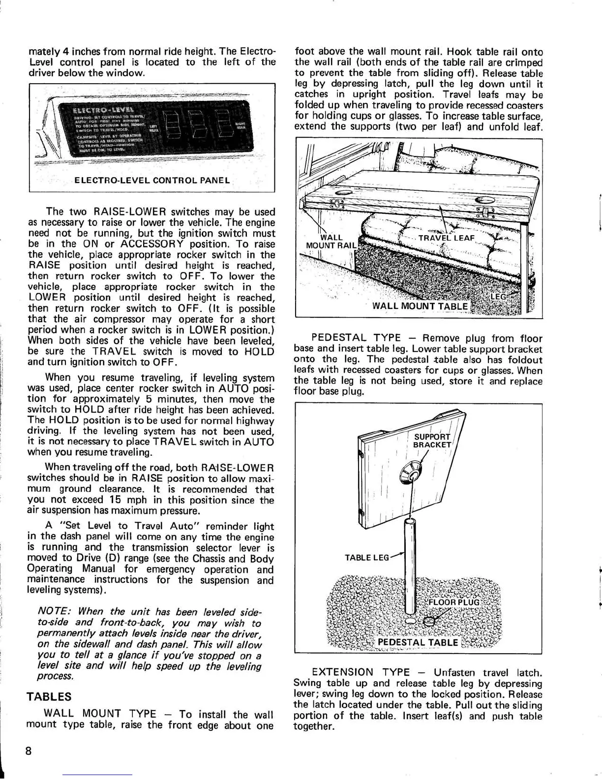
mately 4 inches from normal ride height
. The Electro
-
Level control panel is located to the left of th
e
driver below the window
.
The two RAISE-LOWER switches may be use
d
as necessary to raise or lower the vehicle
. The engin
e
need not be running, but the ignition switch mus
t
be in the ON or ACCESSORY position
. To rais
e
the vehicle, place appropriate rocker switch in th
e
RAISE position until desired height is reached
,
then return rocker switch to OFF
. To lower th
e
vehicle, place appropriate rocker switch in th
e
LOWER position until desired height is reached
,
then return rocker switch to OFF
. (It is possibl
e
that the air compressor may operate for a shor
t
period when a rocker switch is in LOWER position
.
)
When both sides of the vehicle have been leveled
,
be sure the TRAVEL switch is moved to HOL
D
and turn ignition switch to OFF
.
When you resume traveling, if leveling syste
m
was used, place center rocker switch in AUTO posi-
tion for approximately 5 minutes, then move th
e
switch to HOLD after ride height has been achieved
.
The HOLD position is to be used for normal highwa
y
driving
. If the leveling system has not been used
,
it is not necessary to place TRAVEL switch in AUT
O
when you resume traveling
.
When traveling off the road, both RAISE-LOWE
R
switches should be in RAISE position to allow maxi
-
mum ground clearance
. It is recommended tha
t
you not exceed 15 mph in this position since th
e
air suspension has maximum pressure
.
A "Set Level to Travel Auto" reminder ligh
t
in the dash panel will come on any time the engin
e
is running and the transmission selector lever i
s
moved to Drive (D) range (see the Chassis and Bod
y
Operating Manual for emergency operation an
d
maintenance instructions for the suspension an
d
leveling systems)
.
NOTE
: When the unit has been leveled side-
to-side and front-to-back, you may wish t
o
permanently attach levels inside near the driver
,
on the sidewall and dash panel
. This will allo
w
you to tell at a glance if you've stopped on
a
level site and will help speed up the levelin
g
process
.
TABLE
S
WALL MOUNT TYPE — To install the wal
l
mount type table, raise the front edge about one
foot above the wall mount rail
. Hook table rail ont
o
the wall rail (both ends of the table rail are crimpe
d
to prevent the table from sliding off)
. Release tabl
e
leg by depressing latch, pull the leg down until i
t
catches in upright position
. Travel leafs may b
e
folded up when traveling to provide recessed coaster
s
for holding cups or glasses
. To increase table surface
,
extend the supports (two per leaf) and unfold leaf
.
PEDESTAL TYPE — Remove plug from floo
r
base and insert table leg
. Lower table support bracke
t
onto the leg
. The pedestal table also has foldou
t
leafs with recessed coasters for cups or glasses
. Whe
n
the table leg is not being used, store it and replac
e
floor base plug
.
EXTENSION TYPE — Unfasten travel latch
.
Swing table up and release table leg by depressin
g
lever
; swing leg down to the locked position
. Releas
e
the latch located under the table
. Pull out the slidin
g
portion of the table
. Insert leaf(s) and push tabl
e
together
.
8