11
D1030 - SIL 2 Switch / Proximity Detector Repeater Relay Output G.M. International ISM0008-17
Input Output Input Output
Output Input Output Input
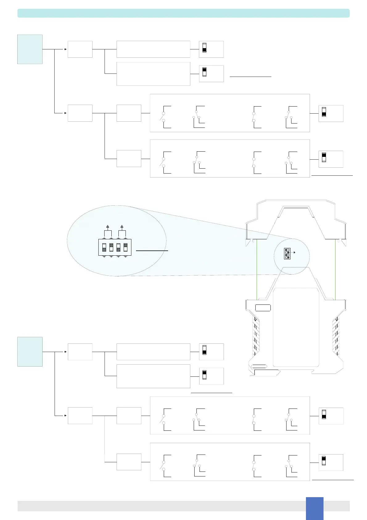
A configuration DIP switch is located on component side of pcb. This switch allows the configuration of input/output relationship, fault detection functions and operating mode.
Configuration
Dip switch configuration
D1030D
2
1
CH1
Setting
Line fault
detection
ON
IN / OUT
Operation
NO-NE or
NC-ND
NO-ND or
NC-NE
ON
1
OFF
4
4
3
3
Disabled
(contact / proximity sensor)
Enabled
(proximity sensor or contact
with terminating line resistor)
ON
13
2
OFF
NO
14
1
2
8
NE
OR
NC
13
14
1
2
8
ND
13
NO
14
1
2
8
NE
OR
NC
13
14
1
2
8
ND
Side A Panel View
Input Output Input Output
Output Input Output Input
CH2
Setting
Line fault
detection
ON
IN / OUT
Operation
NO-NE or
NC-ND
NO-ND or
NC-NE
ON
OFF
Disabled
(contact / proximity sensor)
Enabled
(proximity sensor or contact
with terminating line resistor)
15
OFF
NO
16
5
6
7
NE
OR
NC
15
16
5
6
7
ND
15
NO
16
5
6
7
NE
OR
NC
15
16
5
7
6
ND
Factory settings
For SIL applications.
For SIL applications.
For SIL applications.
For SIL applications.
123
4
ON
CH1 CH2
OFF ON OFF ON
 Loading...