12
D1030 - SIL 2 Switch / Proximity Detector Repeater Relay Output G.M. International ISM0008-17
1234
ON
CH1
OFF ON OFF OFF
4
4
1
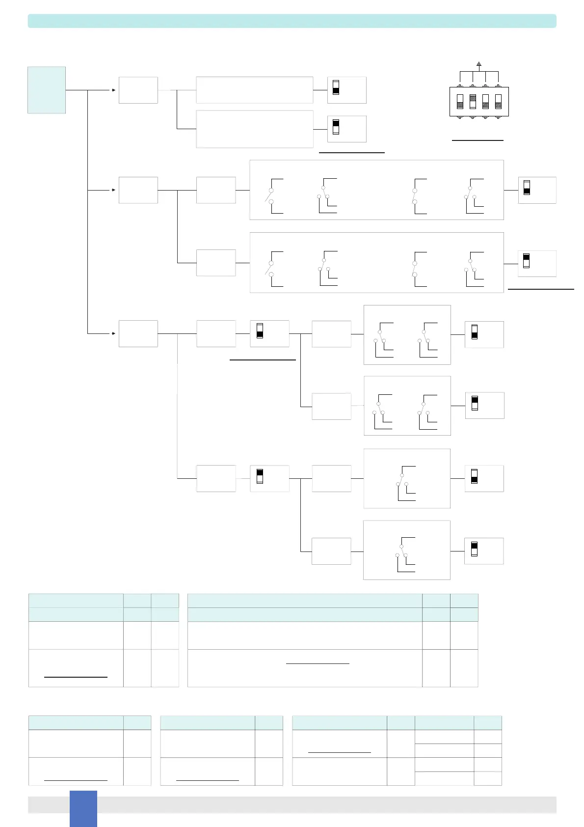
CH
Setting
Line fault
detection
IN / OUT
Operation
NO-NE or
NC-ND
NO-ND or
NC-NE
1
4
4
3
3
Dip switch configuration
D1030S
B Output
Operation
Normal
Parallel
Mode
Reverse
Mode
OFF
ON
Fault
Output
ON
ND
Mode
NE
Mode
OFF
ON
OFF
Configuration
Input Output Input Output
Output Input Output Input
2
ON
13
2
OFF
NO
14
1
2
8
NE
OR
NC
13
14
1
2
8
ND
13
NO
14
1
2
8
NE
OR
NC
13
14
1
2
8
ND
ON
OFF
Disabled
(contact / proximity sensor)
Enabled
(proximity sensor or contact
with terminating line resistor)
Out B Out A
1
2
8
5
6
7
Out A
1
2
8
Out B
5
6
7
No Fault
5
6
7
5
6
7
NE
NE
NE
ND
ND
NE
No Fault
D1030D Configuration Summary Table
Channel
IN/OUT Operation
NO-NE or NC-ND
NO-ND or NC-NE
(For SIL applications.)
SW2
OFF
SW4
OFF
ON
1
2
Channel
Line fault detection
Disabled
(contact/proximity sensor)
Enabled (For SIL applications.)
(proximity sensor or contact with terminating line resistor,
detects field open circuit and short circuit de-energizing output)
SW1 SW3
1
2
ON
OFF OFF
ON ON
IN/OUT Operation
NO-NE or NC-ND
NO-ND or NC-NE
(For SIL applications.)
SW2
OFF
ON
Line fault detection
Disabled
Enabled
(For SIL applications.)
SW1
OFF
ON
B Output Operation
Normal
(For SIL applications.)
Fault Output
SW3
OFF
ON
Mode
Direct
Reverse
ND
NE
SW4
OFF
ON
OFF
ON
D1030S Configuration Summary Table
For SIL applications.
For SIL applications.
Factory settings
For SIL applications.
 Loading...