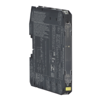
The D5090S is a single-channel SIL 3 relay output module designed for switching safety-related circuits in high-risk industries, compliant with IEC 61508:2010 Ed.2. It provides isolation between input and output contacts and is suitable for normally energized (NE) loads. The module offers two normally open (NO) contacts for the NE load and one normally closed (NC) contact for service purposes, enabling the NE load to be switched on both supply lines.
Function Description:
The D5090S operates in Low Demand mode as a Type A module with a Hardware Fault Tolerance (HFT) of 0. In its primary functional safety application, the relay module is energized during normal operation with an NE load. Upon an alarm or process request, the module de-energizes to a safe state, thereby de-energizing the load. The module supports three mutually exclusive monitoring circuits, selectable via DIP-Switch programming:
- Line Input Monitoring: This feature allows for DCS/PLC line monitoring, including pulse testing, with an internal circuit preventing relay and LED flickering.
- Low Voltage Input Monitoring: When enabled, the module presents a high impedance state to the control unit if the driving voltage falls below a specified threshold.
- Short Circuit Fault Detection: This enables the DCS/PLC to detect short circuit faults within the module.
The module's failure behavior is defined as follows:
- Fail-Safe State: The output load is de-energized.
- Fail Safe: A failure causing the system to transition to the defined fail-safe state without a process demand.
- Fail Dangerous: A failure mode where the module does not respond to a process demand (i.e., cannot reach the defined fail-safe state), causing the output load to remain energized.
- "No effect" failures: Failure modes of components that are part of the safety function but do not contribute to safe or dangerous failures. These are excluded from SFF calculations.
- "Not part" failures: Failure modes of components not part of the safety function but included in the circuit diagram for completeness. These are also excluded from SFF calculations.
Important Technical Specifications:
- Input: 24 Vdc nominal (21.6 to 27.6 Vdc), reverse polarity protected, with ripple ≤ 5 Vpp.
- Current Consumption @ 24 V: 35 mA (relay energized, line input monitoring disabled), 45 mA (relay energized, line input monitoring enabled), typical.
- Power Dissipation: 0.85 W (relay energized, line input monitoring disabled), 1.1 W (relay energized, line input monitoring enabled), typical.
- Isolation (Test Voltage): Input / All Outputs 2.5 KV; Out 1 / Out 2: 500V.
- Output: One voltage-free SPDT relay contact (Out 1, terminals 7-11) and one voltage-free SPST relay contact (Out 2, terminals 8-12). A service load output (NC contact, terminals 9-10) is also provided, which is not SIL-rated.
- Contact Material: Ag Alloy (Cd free), gold plated.
- Contact Rating: 5 A 250 Vac 1250 VA, 5 A 250 Vdc 140 W (resistive load), 1 A 24 Vdc, 220 mA 125 Vdc, 110 mA 250 Vdc for UL. Minimum switching current 1 mA.
- Contact Inrush Current: 6 A at 24 Vdc, 250 Vac.
- Mechanical/Electrical Life: 5 x 10^6 / 3 x 10^4 operations, typical.
- Operate / Release Time: 55 / 30 ms, typical.
- Frequency Response: 10 Hz maximum.
- Environmental Conditions:
- Operating Temperature: -40 to +70 °C, relative humidity 95%, up to 55 °C.
- Storage Temperature: -45 to +80 °C.
- Max Altitude: 2000 m a.s.l.
- Safety Description: ATEX, IECEx/INMETRO: Ex ec nC IIC T4 Gc; UL/C-UL: NI/1/2/ABCD / T4; FM/FMC: NI/1/2/ABCD/T4, 1/2/Ex nA nC / IIC/T4; EAC-EX: 2Ex nA nC IIC T4 Gc X; CCC: Ex ec nC IIC T4 Gc; UKR TR n. 898: 2ExnAnCIICT4 X. Non-sparking electrical equipment.
- PFDavg (1 year): 7.01 E-06 for Tproof = 14/20 yrs (≤10% of total SIF), with an SFF of 99.17% for NE Load.
- Systematic Capability: SIL 3.
- Weight: Approximately 125 g.
- Dimensions: Width 12.5 mm, Depth 123 mm, Height 120 mm.
- Protection Class: IP 20.
Usage Features:
- Mounting: The D5090S can be mounted on standard EN/IEC60715 TH 35 DIN-Rail or on customized Termination Boards in Safe Area/Non Hazardous Locations or Zone 2, Group IIC T4 or Class I, Division 2, Group A,B,C,D, T4 or Class I, Zone 2, Group IIC, T4. It can be installed in any orientation within the specified ambient temperature range.
- Simplified Installation: Utilizes standard DIN-Rail and plug-in terminal blocks or customized Termination Boards.
- Electrical Connection: Features polarized plug-in disconnect screw terminal blocks that accommodate conductors up to 2.5 mm² (13 AWG). Connections can be made to a powered unit without damage (for Zone 2 installations, verify the area is non-hazardous before servicing). A torque value of 0.5-0.6 Nm is recommended for terminal blocks. For USA and Canada, use cables suitable for at least 85°C.
- DIP Switch Configuration: An eight-position DIP Switch on the PCB allows selection of four mutually exclusive configurations for line input monitoring, low voltage input monitoring, short circuit fault detection, and T-proof relay testing.
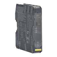
- Status Indication: A "RELAY STATUS" yellow LED indicates when the input is powered and the relay is energized.
- Compatibility: CE mark compliant, conforming to Directives 2014/34/EU ATEX, 2014/30/EU EMC, 2014/35/EU LVD, 2011/65/EU RoHS.
- Approvals: Certified by TÜV for Functional Safety (IEC61508:2010 Ed.2), ATEX, IECEx, UL & C-UL, FM & FM-C, INMETRO, EAC-EX, CCC, UKR TR n. 898, DNV, and KR for maritime applications.
Maintenance Features:
- Proof Test Procedure: A detailed proof test procedure is provided to reveal dangerous undetected faults. This involves bypassing the safety-related PLC, verifying input-to-output functionality across the voltage range, and checking ohmic continuity of contacts using internal DIP-switches to simulate relay coil short circuits. This test reveals almost 99% of all possible Dangerous Undetected failures.
- Servicing: Disconnect power before servicing or unless the area is known to be non-hazardous. Remove power before opening the case.
- Cleaning: The enclosure provides an IP20 minimum degree of protection. For cleaning, use only a cloth lightly moistened by a mixture of detergent in water. Avoid any liquid penetration to prevent damage.
- Repair: The unit cannot be repaired by the end user and must be returned to the manufacturer or authorized representative. Unauthorized modifications are prohibited.
- External Protection: To prevent relay contacts from damage, an external protection (fuse or similar) should be connected, chosen according to the relay breaking capacity diagram from installation instructions.
- Electrostatic Hazard: To avoid electrostatic hazards, the enclosure must be cleaned only with a damp or antistatic cloth.
- Installation Environment: When installed in EU Zone 2, the unit must be in an enclosure providing a minimum ingress protection of IP54. For Class I, Division 2 Hazardous Locations, a supplemental AEx or Ex enclosure with IP54 protection is required. The enclosure must have a door or cover accessible only by a tool. The end user is responsible for ensuring the operating temperature is not exceeded.