2
D5090 - 5 A SIL 3 Relay Output Module for NE Load G.M. International ISM0109-16
General Description: The single channel Relay Output, D5090S is a relay module suitable for the switching of safety related circuits, up to SIL 3 level according to IEC 61508:2010 Ed.2
for high risk industries. It provides isolation between input and output contacts.
Three mutually exclusive (by DIP-Switch programming) monitoring circuits are provided:
1) line input monitoring, to allow DCS/PLC line monitoring function: when enabled, the module permits a wide compatibility towards different DCS/PLC. Driving line pulse testing,
executed by DCS/PLC, is permitted by a dedicated internal circuit, to prevent relay and LED flickering;
2) low voltage input monitoring: when enabled, the module reflects a high impedance state to the control unit when the driving voltage is below the specified threshold;
3) short circuit fault detection: when enabled, it allows DCS/PLC to detect short circuit fault of module.
D5090S provides two NO contacts for normally energized load and a NC contact for service purpose, in order to switch the NE load on both supply lines.
See the following pages for Functional Safety applications with related SIL value.
Mounting on standard DIN-Rail or on customized Termination Boards, in Safe Area / Non Hazardous Location or in Zone 2 / Class I, Division 2 or Class I, Zone 2.
Functional Safety Management Certification:
G.M. International is certified by TUV to conform to IEC61508:2010 part 1 clauses 5-6 for safety related systems up to and included SIL3.
Technical Data
Characteristics
Input: 24 Vdc nom (21.6 to 27.6 Vdc) reverse polarity protected, ripple within voltage limits ≤ 5 Vpp.
The following monitoring circuits are mutually exclusive:
1) Line input monitoring (DIP-Switch selectable): to allow DCS/PLC line monitoring function (pulse test).
2) Voltage monitoring (DIP-Switch selectable): ≥ 21.6 Vdc for normal operation, ≤ 17 Vdc reflects a high impedance (≤ 10 mA consumption) to the control device.
3) Short circuit fault detection (DIP-Switch selectable): to allow DCS/PLC to detect short circuit fault of module.
Current consumption @ 24 V: 35 mA with relay energized and line input monitoring disabled, 45 mA with relay energized and line input monitoring enabled, typical.
Power dissipation: 0.85 W with 24 V input voltage, relay energized and line input monitoring disabled, 1.1 W with 24 V input voltage, relay energized and line input monitoring
enabled, typical.
Isolation (Test Voltage): Input / All Outputs 2.5 KV ; Out 1 / Out 2: 500V.
Output: 1 voltage free SPDT relay contact identified with outputs: Out 1 (NO contact) terminals 7-11 and Service Load Out (NC contact) terminals 9-10;
1 voltage free SPST relay contact identified with output Out 2 (NO contact) terminals 8-12.
Terminals 7-11 (Out 1) and 8-12 (Out 2) are open when relay is de-energized, closed in energized relay condition.
Service load output (not SIL) at terminals 9-10 is normally close when relay is de-energized, open in energized relay condition.
Contact material: Ag Alloy (Cd free), gold plated.
Contact rating: 5 A 250 Vac 1250 VA, 5 A 250 Vdc 140 W (resistive load), 1 A 24 Vdc, 220 mA 125 Vdc, 110 mA 250 Vdc for UL. Min.Switching current 1 mA.
Contact inrush current: 6 A at 24 Vdc, 250 Vac.
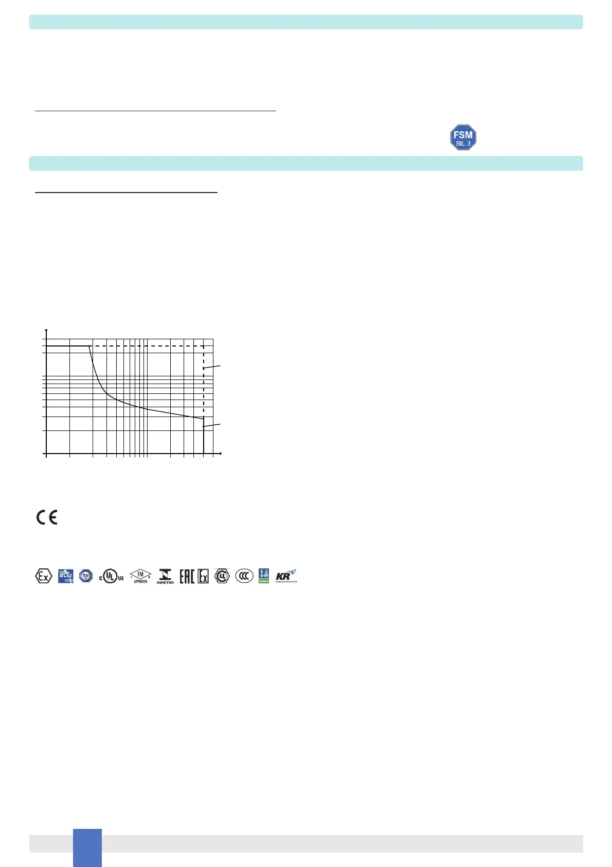
AC / DC Load breaking capacity:
Mechanical / Electrical life: 5 * 10
6
/ 3 * 10
4
operation, typical.
Operate / Release time: 55 / 30 ms, typical.
Frequency response: 10 Hz maximum.
Compatibility:
CE mark compliant, conforms to Directive: 2014/34/EU ATEX, 2014/30/EU EMC, 2014/35/EU LVD, 2011/65/EU RoHS.
Environmental conditions:
Operating: temperature limits – 40 to + 70 °C, relative humidity 95 %, up to 55 °C.
Storage: temperature limits – 45 to + 80 °C.
Max altitude: 2000 m a.s.l.
Safety Description:
ATEX: II 3G Ex ec nC IIC T4 Gc; IECEx / INMETRO: Ex ec nC IIC T4 Gc
UL: NI / I / 2 / ABCD / T4; C-UL: NI / I / 2 / ABCD / T4
FM: NI / I / 2 / ABCD /T4, I / 2 / AEx nA nC / IIC /T4; FMC: NI / I / 2 / ABCD /T4, I / 2 / Ex nA nC / IIC /T4
EAC-EX: 2Ex nA nC IIC T4 Gc X.
CCC: Ex ec nC IIC T4 Gc
UKR TR n. 898: 2ExnAnCIICT4 X.
non-sparking electrical equipment.
-40 °C ≤ Ta ≤ 70 °C.
Approvals:
BVS 10 ATEX E 114 conforms to EN60079-0, EN60079-7, EN60079-15.
IECEx BVS 10.0072 X conforms to IEC60079-0, IEC60079-7, IEC60079-15.
INMETRO DNV 13.0109 X conforms to ABNT NBR IEC60079-0, ABNT NBR IEC60079-7, ABNT NBR IEC60079-15.
UL & C-UL E222308 conforms to UL 61010-1, UL 121201 for UL
and CAN/CSA C22.2 No. 61010-1-12, CSA C22.2 No. 213-17 for C-UL.
FM 3046304 and FMC 3046304C conforms to Class 3600, 3611, 3810, ANSI/ISA-60079-0, ANSI/ISA-60079-15, C22.2 No.142, C22.2 No.213, C22.2 No. 60079-0, C22.2 No. 60079-15.
ЕАЭС RU С-IT.EX01.B.00018/19 conforms to GOST 31610.0, GOST 31610.15.
CCC n. 2020322316000978 conforms to GB/T 3836.1, GB/T 3836.3, GB/T 3834.8
CЦ 16.0036 X conforms to ДСТУ 7113, ДСТУ IЕС 60079-15.
TÜV Certificate No. C-IS-236198-04, SIL 3 conforms to IEC61508:2010 Ed.2.
SIL 3 Functional Safety TÜV Certificate conforms to IEC61508:2010 Ed.2, for Management of Functional Safety.
DNV Type Approval Certificate No. TAA00001U0 and KR No.MIL20769-EL002 Certificates for maritime applications.
Mounting: EN/IEC60715 TH 35 DIN-Rail or on customized Termination Board.
Weight: about 125 g.
Connection: by polarized plug-in disconnect screw terminal blocks to accommodate terminations up to 2.5 mm
2
.
Location: installation in Safe Area/Non Hazardous Locations or Zone 2, Group IIC T4 or Class I, Division 2, Group A,B,C,D, T4 or Class I, Zone 2, Group IIC, T4.
Protection class: IP 20.
Dimensions: Width 12.5 mm, Depth 123 mm, Height 120 mm.
0.20.0
V (V)
I (A)
10
20
30
40
50
100
0.3 0.4 0.5 1 2 3
Resistive
Load
200
4
300
250
0.1
56
DC
resistive
AC
Resistive
 Loading...