4
D5290 - 10 A SIL 3 Relay Output Module for NE Load G.M. International ISM0111-8
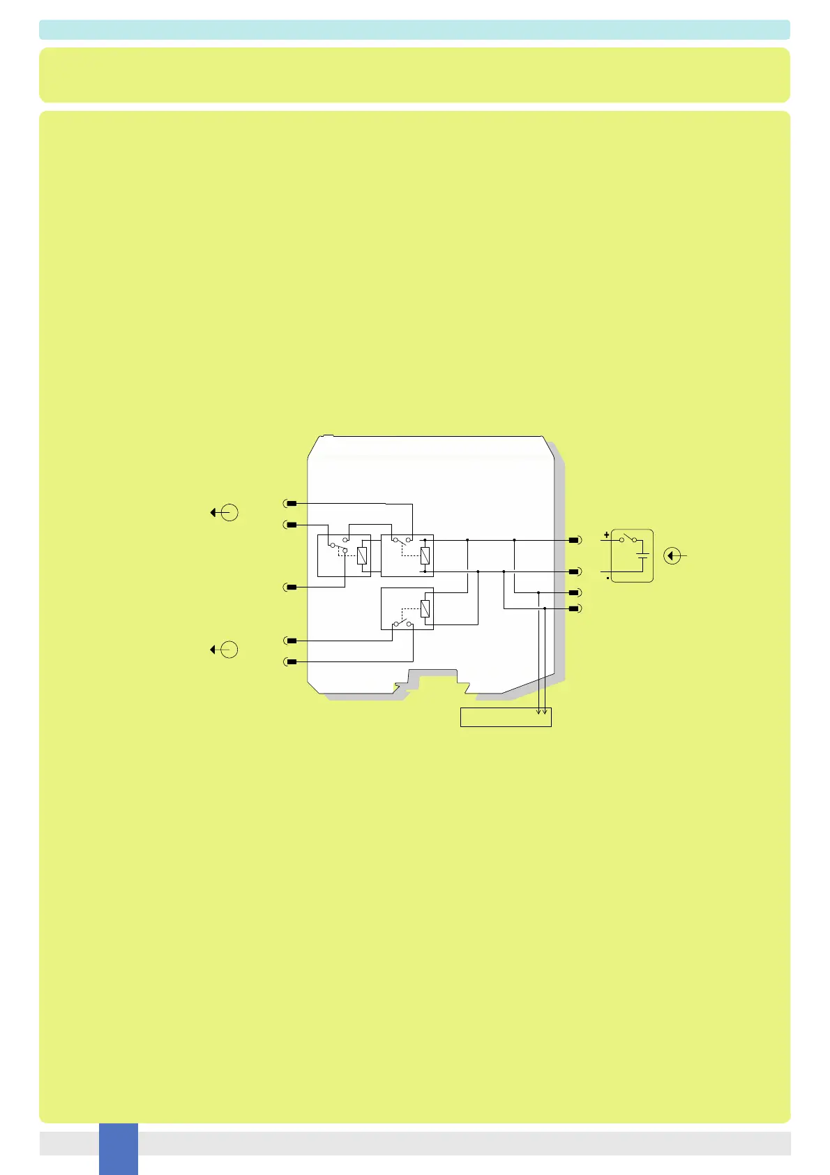
Function Diagram
SAFE AREA, ZONE 2 GROUP IIC T4,
NON HAZARDOUS LOCATIONS, CLASS I, DIVISION 2,
GROUPS A, B, C, D T-Code T4, CLASS I, ZONE 2, GROUP IIC T4
Relay contact shown in de-energized position.
Terminals 13-21 and 14-22 are open; terminal 13-15 is closed.
MODEL D5290S
+
Out 1 (NO contact)
(NO2) 21
(CM1) 13
(NC1) 15
In
1
2
3
4
Service Load
Termination
board
connector
Not SIL
Out 2 (NO contact)
(NO1) 14
(NO3) 22
See the following pages for Functional Safety applications with related SIL value.
To prevent relay contacts from damaging, connect an external protection (fuse or similar),
chosen according to the relay breaking capacity diagram.