2
D5294 - 5 A SIL 3 NO contact Relay Out Module for NE or F&G/ND Load with full diagnostic and Modbus G.M. International ISM0123-14
Technical Data
Characteristics
Supply: 24 Vdc nom (21.6 to 27.6 Vdc) reverse polarity protected, ripple within voltage limits 5 Vpp, 2 A time lag fuse internally protected.
Current consumption @ 24 V: 40 mA typical, with channel de-energized and no fault.
Power dissipation: 1 W typical.
Isolation (Test Voltage): Output/Input 2.5 KV; Output/Supply 2.5 KV; Output/Fault Outputs 2.5 KV; Output/RS485 Modbus 2.5 KV;
Input/Supply 500 V; Input/Fault Output 1 500 V; Input/Fault Output 2 2.5 KV; Input/RS485 Modbus 500 V; Supply/Fault Output 1 500 V;
Supply/Fault Output 2 2.5 KV; Supply/RS485 Modbus 500 V.
Input: 24 Vdc nom (21.6 to 27.6 Vdc) reverse polarity protected, ripple within voltage limits 5 Vpp.
Current consumption @ 24 V: 40 mA (with mirror and no fault).
Power dissipation @ 24 V: 1 W (with mirror and no fault).
Output: voltage free 2+2 SPST relay contact (2 paralleled contacts in series) at terminals 13-15 and 14-16, close when relay energized, open in de-energized condition.
Contact material: Ag Alloy (Cd free), gold plated.
Contact rating: 5 A 250 Vac 1250 VA, 5 A 250 Vdc 140 W (resistive load). Min.switching current 1 mA.
Contact inrush current: 6 A at 24 Vdc, 250 Vac.
Mechanical / Electrical life: 5 * 10
6
/ 3 * 10
4
operation, typical.
Operate / Release time: 8 / 4 ms typical.
Bounce time NO / NC contact: 3 / 8 ms, typical.
Frequency response: 10 Hz maximum.
Fault detection: load and line short/open circuit monitoring
Short output detection: programmable load resistance (5 to 49 K typical).
Open output detection: programmable load resistance (5 to 49 K typical).
Fault signalling: voltage free NE 1 + 1 SPST relay contacts (closed in normal status),
output de-energized (contacts opened) in fault condition. Fault contact can be reversed via software.
Fault 1 output rating: 500 mA 30 Vac 15 VA, 500 mA 50 Vdc 25 W (resistive load).
Fault 2 output rating: 3 A 250 Vac 750 VA, 3 A 125 Vdc 120 W (resistive load).
Response time: 3/4 sec typical.
Modbus Output: measure data, load and line diagnostic monitoring. Modbus RTU protocol up to 115.2 Kbit/s with RS-485
connection on terminal blocks and Power Bus connector.
Terminating impedance: 100 software selectable,
Transmission speed: 4.8, 9.6, 19.2, 38.4, 57.6, 115.2 Kbit/s.
Transmission cable length: 1200 m up to 93.75 Kbit/s, 1000 m up to 115.2 Kbit/s.
Compatibility:
CE mark compliant, conforms to Directive:
2014/34/EU ATEX, 2014/30/EU EMC, 2014/35/EU LVD, 2011/65/EU RoHS.
Environmental conditions:
Operating: temperature limits – 40 to + 70 °C, relative humidity 95 %, up to 55 °C.
Storage: temperature limits - 45 to + 80 °C.
Safety Description:
ATEX: II 3G Ex nA nC IIC T4 Gc
IECEx / INMETRO / NEPSI: Ex nA nC IIC T4 Gc
FM: NI / I / 2 / ABCD /T4, I / 2 / AEx nA nC / IIC /T4
FMC: NI / I / 2 / ABCD /T4, I / 2 / Ex nA nC / IIC /T4
EAC-EX: 2ExnAnCIICT4 X.
UKR TR n. 898: 2ExnAnCIICT4 X.
non-sparking electrical equipment. -40 °C Ta 70 °C.
Approvals:
BVS 10 ATEX E 114 conforms to EN60079-0, EN60079-15.
IECEx BVS 10.0072 X conforms to IEC60079-0, IEC60079-15
INMETRO DNV 13.0109 X conforms to ABNT NBR IEC60079-0, ABNT NBR IEC60079-15.
UL & C-UL E477485 conforms to ANSI/UL508
FM 3046304 and FMC 3046304C conforms to Class 3600, 3611, 3810, ANSI/ISA-60079-0, ANSI/ISA-60079-15, C22.2 No.142, C22.2 No.213, C22.2 No. 60079-0, C22.2 No. 60079-15.
C-IT.ME92.B.00206 conforms to GOST 30852.0, 30852.14.
C 16.0036 X conforms to 7113, I 60079-15.
GYJ14.1406X conforms to GB3836.1, GB3836.8.
TUV Certificate No. C-IS-236198-04, SIL 3 conforms to IEC61508:2010 Ed. 2.
TÜV Certificate No. C-IS-236198-09, SIL 3 Functional Safety Certificate conforms to IEC61508:2010 Ed.2, for Management of Functional Safety.
SIL 2 conforms to IEC 61511 for Line and Load Diagnostic Functionalities (Pending).
DNV Type Approval Certificate No.A-13625 and KR No.MIL20769-EL002 Certificates for maritime applications.
Patent No. 0001406495 , released on 28/02/2014, valid for 20 years.
Mounting: T35 DIN-Rail according to EN50022, with or without Power Bus or on customized Termination Board.
Weight: about 195 g.
Connection: by polarized plug-in disconnect screw terminal blocks to accommodate terminations up to 2.5 mm
2
.
Location: installation in Safe Area/Non Hazardous Locations or Zone 2, Group IIC T4 or Class I, Division 2, Group A,B,C,D, T4 or Class I, Zone 2, Group IIC, T4.
Protection class: IP 20.
Dimensions: Width 22.5 mm, Depth 123 mm, Height 120 mm.
General Description: The The D5294S is a relay module suitable for the switching of safety related circuits, up to SIL 3 level according to IEC 61508:2010 Ed. 2 for high risk industries.
It provides isolation between input and output contacts. A wide compatibility towards different DCS/PLC is guaranteed: driving line pulse testing, executed by DCS/PLC, is permitted by
a dedicated internal circuit, to prevent relay and LED flickering. Internal relay coil short circuit is detected by the module. D5294S has 2+2 SPST relay contacts connected in parallel
and then in series to avoid spurious trips and to increase availability (see function diagram). High availability SIL 3 Safety Function for NE load or F&G / ND load is available at Terminal
Blocks 13-14. When the driving signal is low (0 Vdc), the relay is de-energized, contacts at terminals 13-15 and 14-16 are open and load is de-energized. When the driving signal is
high (24 Vdc), the relay is energized, contacts at terminals 13-15 and 14-16 are closed, the load is energized. Load is isolated from supply on both polarities: +/AC, -/AC.
Load and Line Diagnostic: Line and load short/open circuit detection is provided, with solenoid resistance measurement, even in presence of series connected diodes.
A patented proprietary resistance measuring technique performs the load short and open circuit diagnosis in de-energized load status, for DC or AC supply systems. Load RMS voltage
(before and after its energization) and current are measured by the module. Load voltage, current and resistance can automatically be acquired from field. User configurable limits set
the minimum and maximum values of load resistance, supply voltage (DC or AC) and load current. Earth leakage detection on both AC phases is available in de-energized load condi-
tion. The fault in the field is directly mirrored to the PLC DO: few systems may exceptionally require an external resistor at terminals 7 and 8. All diagnostic conditions, that detect a fault
on line and load, open the fault relay contacts and are also available from a RS485 Modbus output to identify any specific fault. Diagnostic functions with fault relay NO contacts and
RS485 Modbus output are SIL 2 rated according to IEC 61511. Mounting on standard DIN-Rail, with or without Power Bus, or on customized Termination Boards, in Safe Area / Non
Hazardous Location or in Zone 2 / Class I, Division 2 or Class I, Zone 2.
Functional Safety Management Certification:
G.M. International is certified by TUV to conform to IEC61508:2010
part 1 clauses 5-6 for safety related systems up to and included SIL3.
The module is fully programmable to set the operation parameters from PC by the GM Pocket Portable Adapter PPC5092 via USB serial line and SWC5090 Configurator software.
Measured values and diagnostic alarms can be read on both serial configuration or Modbus output line.
Available diagnostic functions:
Programming
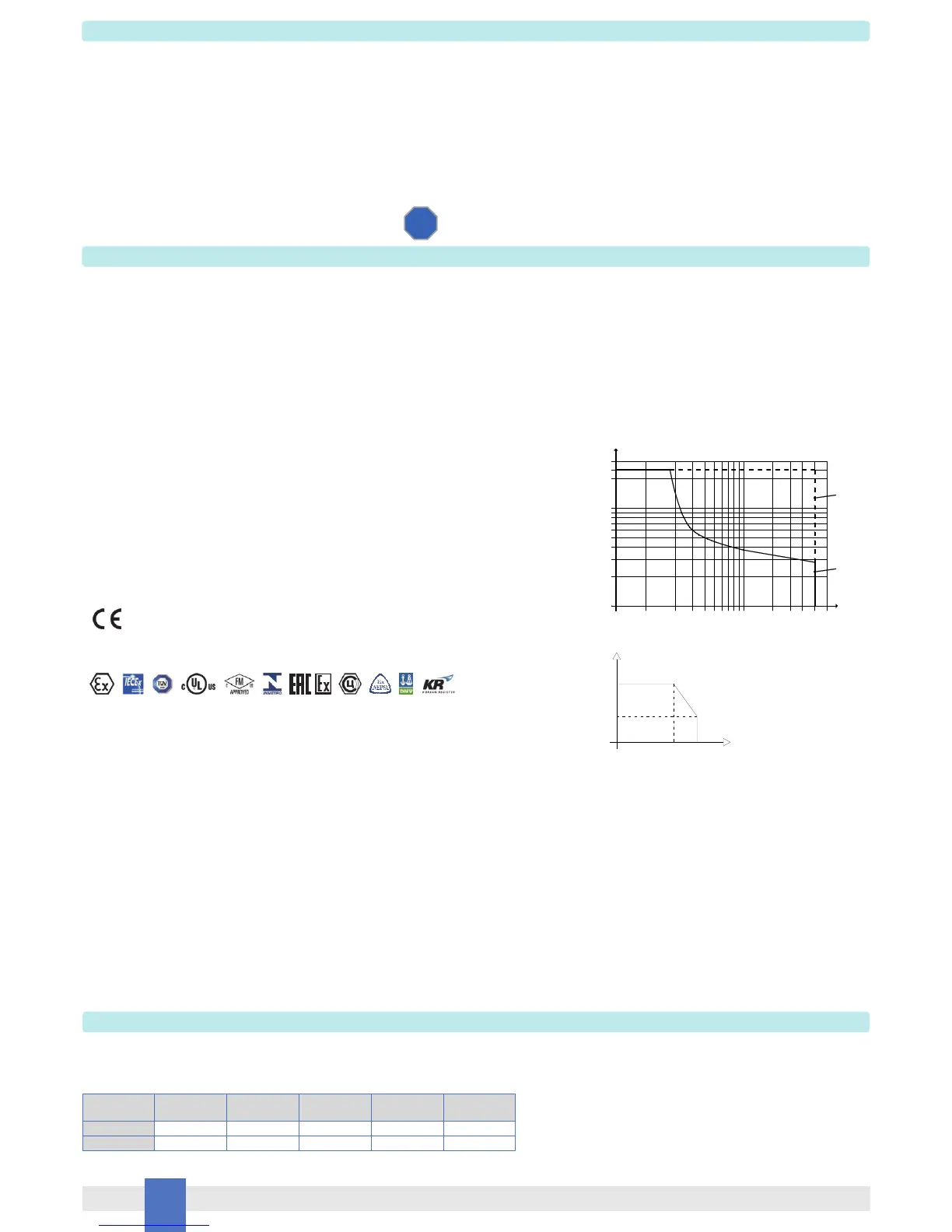
DC Load breaking capacity:
FSM
SIL 3
Load status Load voltage Load open
circuit
Load short
circuit
Load to earth
leakage
Internal coil
short
OFF PF PF PF PF
ON PF PF PF F
F = available function
PF = available function with programmable thresholds
0.20.0
V (V)
I (A)
10
20
30
40
50
100
0.3 0.4 0.5 1 2 3
Resistive
Load
200
4
300
250
0.1
56
DC
resistive
AC
Resistive
5A
2A
60°C
70°C
Tamb
I (contact rating)
 Loading...