10
D5294 - 5 A SIL 3 NO contact Relay Out Module for NE or F&G/ND Load with full diagnostic and Modbus G.M. International ISM0123-14
Warning
Operation
The single channel 5 A Relay Output D5294S is a relay module suitable for the switching of safety related circuits, up to SIL 3 level according to IEC 61508:2010 Ed.2 for high risk
industries. It provides isolation between input and output contacts. D5294S has 2+2 SPST relay contacts connected in parallel and then in series to avoid spurious trip and to increase
availability (see function diagram). High availability SIL 3 Safety Function for NE load or F&G/ND load is available at Terminal Blocks 13-14. When the driving signal is low (0 Vdc), the
relay is de-energized, contacts at terminals 13-15 and 14-16 are open and load is de-energized. When the driving signal is high (24 Vdc), the relay is energized, contacts at terminals
13-15 and 14-16 are closed and the load is energized. Presence of diagnostic circuit power supply, status of input / output channel (energized or de-energized), as well as any type of
fault condition (line and load short/open circuit, relay coil short circuit, etc.) are displayed by related signalling LEDs: green power supply, yellow for status channel and red for fault.
Installation
D5294S is a relay output module housed in a plastic enclosure suitable for installation on T35 DIN-Rail according to EN50022, with or without Power Bus or on customized Termination
Board. D5294S unit can be mounted with any orientation over the entire ambient temperature range. Electrical connection of conductors up to 2.5 mm² are accommodated by polarized
plug-in removable screw terminal blocks which can be plugged in/out into a powered unit without suffering or causing any damage (for Zone 2 installations check the area to be
nonhazardous before servicing). The wiring cables have to be proportionate in base to the current and the length of the cable. On the section “Function Diagram” and enclosure side a
block diagram identifies all connections. Identify the function and location of each connection terminal using the wiring diagram on the corresponding section, as an example:
Connect 24 Vdc power supply positive at terminal “9” and negative at terminal “10”.
Connect positive input at terminal “1” and negative input at “2”.
Connect Fault output 1 (30 V, 500mA) at terminals “3” and “4” and Fault output 2 (250 V, 3A) at terminals “11” and “12”.
Connect A- Modbus RS845 for diagnostic at terminal “5” and B+ at terminal “6”.
Connect positive output NE or F&G/ND load at terminal “13” and negative at terminal “14”.
Connect positive Load Power DC/AC at terminal “15” and negative at terminal “16”.
Connect ground at terminal “21”.
Installation and wiring must be in accordance to the relevant national or international installation standards (e.g. IEC/EN60079-14 Electrical apparatus for explosive gas atmospheres
Part 14: Electrical installations in hazardous areas (other than mines)), make sure that conductors are well isolated from each other and do not produce any unintentional connection.
Connect 2+2 SPST relay contacts checking the load rating to be within the contact maximum rating 5 A 250 Vac 1250 VA, 5 A 250 Vdc 140 W (resistive load). To prevent relay con-
tacts from damaging, connect an external protection (fuse or similar), chosen according to the relay breaking capacity diagram on data sheet. The enclosure provides,
according to EN60529, an IP20 minimum degree of mechanical protection (or similar to NEMA Standard 250 type 1) for indoor installation, outdoor installation requires an additional
enclosure with higher degree of protection (i.e. IP54 to IP65 or NEMA type 12-13) consistent with the effective operating environment of the specific installation. Units must be protected
against dirt, dust, extreme mechanical (e.g. vibration, impact and shock) and thermal stress, and casual contacts. If enclosure needs to be cleaned use only a cloth lightly moistened by a
mixture of detergent in water. Electrostatic Hazard: to avoid electrostatic hazard, the enclosure of D5294S must be cleaned only with a damp or antistatic cloth. Any penetration
of cleaning liquid must be avoided to prevent damage to the unit. Any unauthorized card modification must be avoided. According to EN61010, D5294 must be connected to SELV or
SELV-E supplies. Relay output contact must be connected to load non exceeding category II overvoltage limits. Warning: de-energize main power source (turn off power supply
voltage) and disconnect plug-in terminal blocks before opening the enclosure to avoid electrical shock when connected to live hazardous potential.
D5294S is an electrical apparatus installed into standard EN50022 T35 DIN-Rail located in Safe Area or Zone 2, Group IIC, Temperature Classification T4, Hazardous Area
(according to EN/IEC60079-15) within the specified operating temperature limits Tamb - 40 to +60 °C. D5294S must be installed, operated and maintained only by qualified personnel, in
accordance to the relevant national/international installation standards (e.g. IEC/EN60079-14 Electrical apparatus for explosive gas atmospheres - Part 14: Electrical installations in
hazardous areas (other than mines)), following the established installation rules. De-energize power source (turn off power supply voltage) before plug or unplug the terminal blocks
when installed in Hazardous Area or unless area is known to be nonhazardous. Warning: substitution of components may impair suitability for Zone 2. Warning: de-energize
main power source (turn off power supply voltage) and disconnect plug-in terminal blocks before opening the enclosure to avoid
electrical shock when connected to live
hazardous potential. Explosion Hazard: to prevent ignition of flammable or combustible atmospheres, disconnect power before servicing or unless area is known to be
onhazardous. Failure to properly installation or use of the equipment may risk to damage the unit or severe personal injury. The unit cannot be repaired by the end user and must be
returned to the manufacturer or his authorized representative. Any unauthorized modification must be avoided.
According to IEC 61508-2, the proof test will be performed to reveal dangerous faults which cannot be otherwise detected. This means that it is necessary to specify how dangerous
undetected faults, which have been noted during the FMEDA analysis, can be revealed during the proof test.
When the diagnostic circuits of D5294S are used with the 1 +1 SPST fault relay output, the Proof Test consists of the following steps:
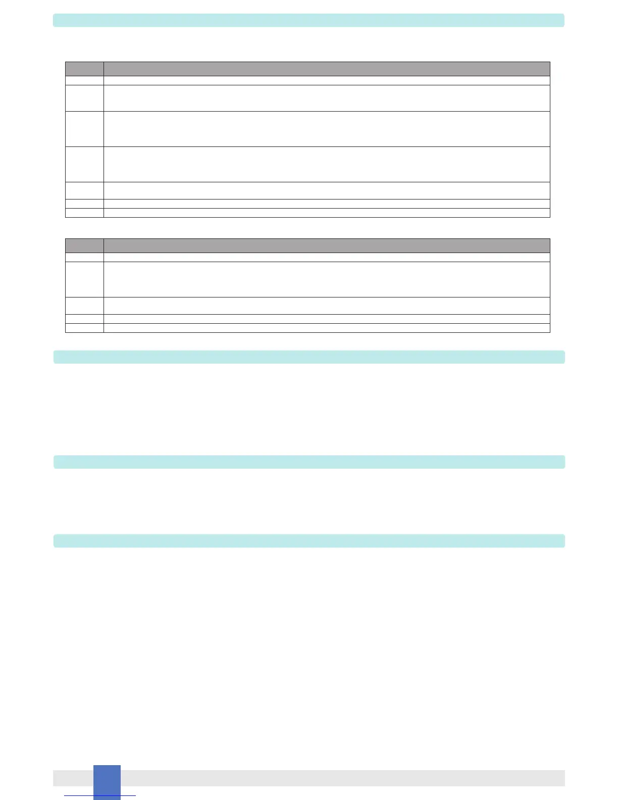
Testing procedure at T-proof
Steps Action
1 Bypass the Safety PLC or take any other appropriate action to avoid a false trip.
2 By means of the configuration software, configure each fault relay output to be energized with closed contacts in normal operation and de-energized with open
contacts when a fault condition occurs. Connect an ohmmeter to each couple of relay contacts and verify that, during the modules normal operation, the fault
relay outputs are energized with presence of ohmic continuity between their contacts.
3 Impose a fault condition to any of the analog measures performed by the modules (for example, if coil integrity is enabled, by means of the SW1 dip-switch, it is
possible to short circuit any of the output relay coils). Verify that, during fault condition, the fault relay outputs are de-energized with absence of ohmic continuity
between their contacts. Finally, remove the fault condition (for example, remove the output relay coil short circuit by means of the SW1 dip-switch) and verify that
the fault relay outputs are switched to the energized state with presence of ohmic continuity between their contacts.
7 Remove the bypass from the Safety-related PLC or restore normal operation.
6 Restore the loop to full operation
5 Shut down ModBus communication and verify that the configuration software indicates a communication error. Finally, restore ModBus communication and verify
that the configuration software still indicates the values of the performed analog measures with a tolerance lower than +/- 20%.
4 Connect the modules to the RS485 ModBus interface and use the configuration software to read the values of the analog measures performed by the modules.
Impose different line and load conditions by means of AC or DC voltage generator and passive or active load and verify that the values detected by means of the
configuration software are within +/- 20% of the imposed values. Perform this test when the modules output relays are both in the energized and de-energized
states.
This test will reveal approximately 99% of the possible Dangerous Undetected failures in the diagnostic circuits of D5294S when the fault relay output is considered.
When the diagnostic circuits of D5294S are used with the ModBus output with RS485 connection, the Proof Test consists of the following steps:
Steps Action
1 Bypass the Safety PLC or take any other appropriate action to avoid a false trip.
2 Connect the modules to the RS485 ModBus interface and use the configuration software to read the values of the analog measures performed by the modules.
Impose different line and load conditions by means of AC or DC voltage generator and passive or active load and verify that the values detected by means of
the configuration software are within +/- 20% of the imposed values. Perform this test when the modules output relays are both in the energized and de-
energized states.
3 Shut down ModBus communication and verify that the configuration software indicates a communication error. Finally, restore ModBus communication and verify
that the configuration software still indicates the values of the performed analog measures with a tolerance lower than +/- 20%.
5 Remove the bypass from the Safety-related PLC or restore normal operation.
4 Restore the loop to full operation
This test will reveal approximately 99% of the possible Dangerous Undetected failures in the diagnostic circuits of D5294S when the ModBus output is considered.

 Loading...