3
D5294 - 5 A SIL 3 NO contact Relay Out Module for NE or F&G/ND Load with full diagnostic and Modbus G.M. International ISM0123-14
Ordering information
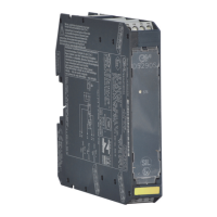
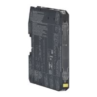
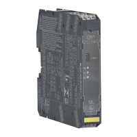
Front Panel and Features
SIL 3 according to IEC 61508:2010 Ed. 2 for Tproof = 13 / 20 yrs (10% / >10 % of total SIF) for NE Load,
with PFDavg (1 year) 7.55 E-06, SFF 99.29%
SIL 3 according to IEC 61508:2010 Ed. 2 for Tproof = 6 / 20 yrs (10% / >10 % of total SIF) for F&G/ND Load,
with PFDavg (1 year) 1.49 E-05, SFF 97.52%
SIL 2 according to IEC 61511 for Tproof = 1 / 5 yrs (10% / >10 % of total SIF) for diagnostic with fault relay NO contact,
with PFDavg (1 year) 5.86 E-04, SFF 70.54%
SIL 2 according to IEC 61511 for Tproof = 2 / 10 yrs (10% / >10 % of total SIF) for diagnostic with RS485 Modbus out,
with PFDavg(1 year) 3.85 E-04, SFF 73.82%
Systematic capability SIL 3.
Installation in Zone 2 / Division 2.
Compatible with DCS/PLC pulse testing.
Internal relay coil short circuit detection.
Line and Load short/open circuit detection.
The fault in the field is directly mirrored to the PLC DO.
Solenoid resistance measurement even in presence of serial connected diodes (patented resistance measuring technique).
RMS voltage (before and after load energization) and load current measurement.
Automatic acquisition of voltage, current and load resistance values.
Earth leakage detection on both ac phases in de-energized load condition.
5 A high availability SIL 3 contacts for NE or F&G/ND load.
6 A inrush current at 24 Vdc / 250 Vac.
Input/Output/Supply isolation.
EMC Compatibility to EN61000-6-2, EN61000-6-4, EN61326-1, EN61326-3-1 for safety system.
ATEX, IECEx, UL & C-UL, FM & FM-C, INMETRO, EAC-EX, UKR TR n. 898, NEPSI, TÜV Certifications.
TÜV Functional Safety Certification.
Type Approval Certificate DNV and KR for maritime applications.
Simplified installation using standard DIN-Rail and plug-in terminal blocks, with or without Power Bus, or customized Termination Boards.
Model: D5294S
Power Bus and DIN-Rail accessories:
Connector JDFT050 Cover and fix MCHP196
Terminal block male MOR017 Terminal block female MOR022
Operating parameters are programmable from PC by the GM Pocket Portable Adapter
PPC5092 via USB serial line and SWC5090 Configurator software.
Terminal block connections
4 3 2 1
8 7 6 5
12 11 10 9
13 14 15 16
21 22 23 24
(SIL 3) + Output NE Load or F&G/ND Load
SAFE AREA
(SIL 3) - Output NE Load or F&G/ND Load
+ Load Power DC/AC
13
14
15
+ Input
1
- Input
2
Fault Output 1 (30 V, 500 mA)
3
Fault Output 1 (30 V, 500 mA)
4
- Load Power DC/AC
16
Earth
Not used
Not used
21
22
23
A- Modbus Input/Output RS485
5
B+ Modbus Input/Output RS485
6
(Optional external resistor)
7
(Optional external resistor)
8
Not used
24
+ Power Supply 24 Vdc
9
- Power Supply 24 Vdc
10
Fault Output 2 (250 V, 3 A)
11
Fault Output 2 (250 V, 3 A)
12
 Loading...