4
D5294 - 5 A SIL 3 NO contact Relay Out Module for NE or F&G/ND Load with full diagnostic and Modbus G.M. International ISM0123-14
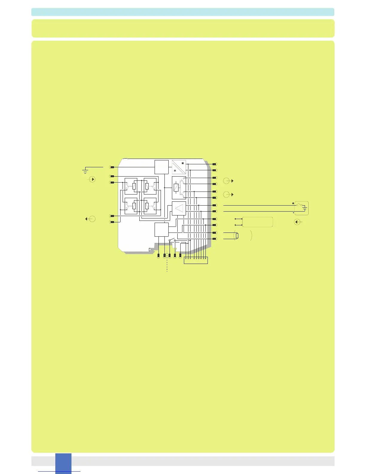
Function Diagram
SAFE AREA, ZONE 2 GROUP IIC T4,
NON HAZARDOUS LOCATIONS, CLASS I, DIVISION 2,
GROUPS A, B, C, D T-Code T4, CLASS I, ZONE 2, GROUP IIC T4
All relay contacts are shown
in de-energized position
To prevent relay contacts from damaging, connect an external protection (fuse or similar),
chosen according to the relay breaking capacity diagram.
MODEL D5294S
+ 15
- 16
+ 13
Load Power DC/AC
11
12
1
2
9 +
10 -
3
4
- 14
(SIL 3) Out
21
Power and
Fault Bus
+
-
F
Modbus RS485
for diagnostic
A-B+
Load and
Line
Diagnostic
Supply 24 Vdc
In
+
Fault Out 2
(250 V, 3 A)
A -
B +
MODBUS
IN/OUT RS485
Fault Out 1
(30 V, 500 mA)
Termination
board
connector
Modbus
RS485
7
8
5
6
NE or F&G/ND Load
external
resistor
Optional
(SIL 2)
(SIL 2)
(SIL 2)
(SIL 2)
(SIL 2)
for Modbus RS485