5
gpelectric.com
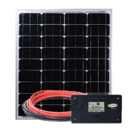
GP-ECO-80
2.0 Wiring Modules with MC4 Cables
Solar Kits with MC4 cables contain a potted or sealed junction box with a positive and negative MC4
connector. This is referred to as an MC4 junction box. MC4 connectors are either positive or negative and
each connector has its polarity symbol embossed close to the connection point. To extend a cable from an
MC4 junction box, a polarity opposite connector must be used. E.G. a negative connector must plug into
a positive connector in order to extend it. Please remember, the polarity of an MC4 cable wire run is the
polarity symbol on the connector closest to the MC4 junction box. It is advisable to attach a polarity sticker to
the positive extension cable in order to avoid confusion during installation.
Note: It is recommeded to double check polarity with a volt meter prior to hooking up the controller
2.1 Installing your 80 watt Eco Kit (GP-ECO-80)
Solar Kits containing a single module with MC4 cables will be equipped with a single 50’ MC4 power cable that
has both a male and female MC4 connection. This cable is meant to be cut in half leaving you with a 25’ cable
with a male MC4 and a 25’ cable with a female MC4 connection. Refer to Section 8, Diagram-1, “MC4 Power
Cables for RV Kits.”
3.0 Routing Power Cable through the Fridge Vent
Locate the refrigerator vent on the roof of the RV. Remove vent cover to gain access to the duct opening. Refer
to Figure 1. Retain vent-fastening hardware.
3.1 Method 1 – Hole in Side of Vent
Drill a hole through the side of the vent (5/8” hole). Insert a rubber grommet (not included) into the hole. Insert the
power cable (already wired to the solar module) through the hole and carefully route it to the battery. Be certain
to leave enough slack to allow cable routing from module to vent along desired path.
3.2 Method 2 – Through Screen Grid
1. Thread power cable (already wired to solar module) carefully through the screen and into opening. Enlarge
screen grid hole if necessary.
2. Avoid strapping the power cable to existing wire between the module and the battery. Allowing a few inches
of space between the power cable and existing wire will lessen the chance of voltage loss through thermal
conduction. Use cable clamps with the #8 self-tapping screws and/or tie wraps every few feet along RV roof
and interior route to battery.
3. Ensure all penetrations into the RV roof are watertight. Use an appropriate sealant as recommended by your
RV Dealer to seal holes wherever necessary.
4. Replace vent cover.
4.0 Mounting the Solar Module
Solar modules may be horizontally mounted to the roof using the included mounting hardware. An optional
adjustable roof mount (ARM-UNI) is also available.
4.1 Using the Mounting Feet
1. Assemble the mounting feet onto the ends of the solar module using the 1/4” bolts, washers and nuts as
shown in Figure 2.
2. Tighten nuts securely using a 7/16” wrench.
3. Place the module in a location that follows the criteria listed here:
• Select a location where the mounting surface is at least 1/2” thick and strong enough to support mounting
hardware, the solar module and wind loads
• Minimize distance between the location of the solar module and the location where the power cable
will enter the vehicle to connect to the battery
• Place the module lengthwise along the roof to reduce wind loading on vehicles (if applicable)
• Avoid internal wiring when selecting the spots for drilling the four mounting holes
• Ensure obstacles, such as air conditioners, will not shade the solar module
Note: Place module so that you have room to expand the current system if needed.
4. Mark the mounting hole locations by using a pencil to trace through the holes in the mounting feet. Drill
mounting holes only one inch deep with a 3/8” drill bit.
5. Use the appropriate sealant as recommended by your RV Dealer to ensure a watertight installation.
6. Gently insert the well-nuts into the drill holes so that only the topmost ange part remains above the rooine.
Be careful not to push well-nuts through the holes.
Caution:
The vent screen may have sharp
edges or burrs.
Figure 1
Vent
Screen
Refrigerator
Vent Cover
Solar
Module
Cable
Clamps
Method 2
Method 1
Solar
Module
1/4” Flat
Washer
1/4’ Lock
Washer
1/4’ Bracket
Bolt
Mounting
Foot
RV
Roof
Figure 2
1/4” Nut
 Loading...