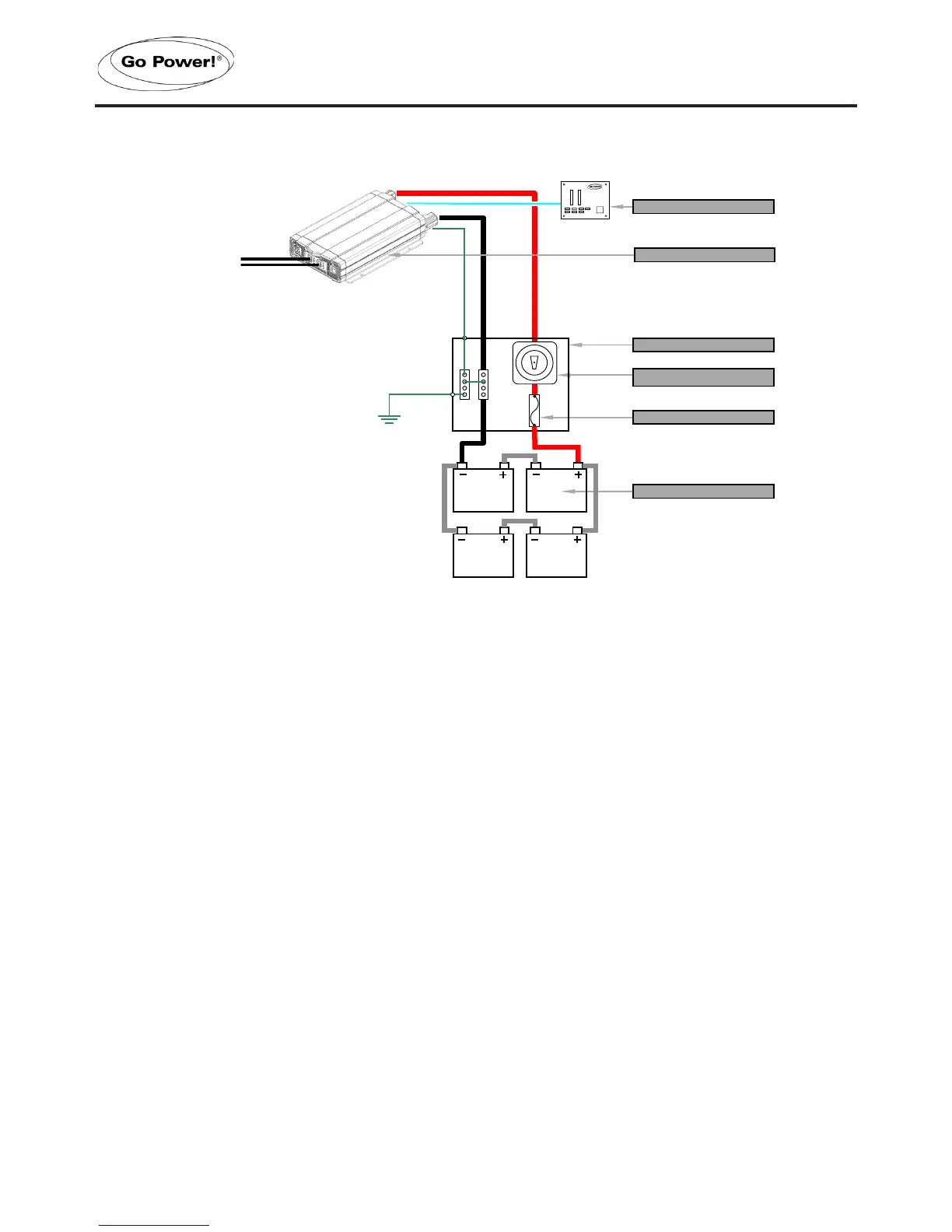
The following points must be observed for the DC Wiring.
•
The DC positive and negative cables connected to the GP-ISW from the battery
bank should be linked together with zip ties or electrical tape every 6”. This helps
to reduce radio frequency interference and reduces the eects of inductance both
of which improve the Inverter waveform and reduces the wear of the Inverters
lter capacitors.
• To ensure optimum Inverter performance the number of connections between
the battery bank and the GP-ISW unit should be minimized except from the
over-current and battery disconnect devices. All additional connection points
will cause extra voltage drops.
• The Battery bank voltage must match the DC voltage required by the GP-ISW,
which is 12V or 24V (note that the Inverter is either 12V or 24V, and is not
switchable.
•
All DC cable wire terminations should use a crimped and sealed copper ring
terminal lugs.
• Make sure all cables have a smooth bend radius and no kinks are present.
•
Colour code all DC Cables coming to / from the battery bank. Use coloured
electrical tape or heat shrink tubing. Red for positive (+), Black for negative (-)
and Green for DC ground.
 Loading...