gpelectric.com | [page 25]
To help prevent seizing and corrosion around the terminals the use of an anti-seize lubricant
is highly recommended. Apply the antioxidant grease or spray after all the connections are
made and tightened.
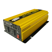
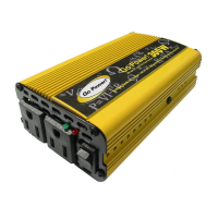
3.3.5 WIRING THE INVERTER TO THE BATTERIES
WARNING: Lethal currents will be present if the positive and negative cables attached
to the battery bank touch each other. During the installation and wiring process, ensure
the cable ends are insulated or covered to prevent shorting the cables.
WARNING: DO NOT connect the DC Wires from the battery bank to the GP-ISW until all
the DC and AC wiring is complete and the AC overcurrent protection has been installed.
The GP-ISW comes in 12V or 24V versions. Make sure the battery bank is wired in series,
parallel, or series-parallel to match the voltage of your inverter. The interconnecting wires
between the individual batteries must be sized and rated exactly the same as those used
between the battery bank and Inverter.
To ensure the best performance from your Inverter system, batteries should be the same size,
type, rating and age. Do not use old or untested batteries.
DC Positive and Negative Wires
•
Connect the negative cable from the battery bank negative terminal to the
Inverters negative terminal. Mount the DC circuit breaker or fuse assembly
and leave open (no power to the GP-ISW). Connect the positive cables from
the circuit breaker / fuse to the battery bank and to the Inverters positive terminal
(Note: DC circuit breaker and fuse not included).
•
Ensure the DC wire connections are ush on the surface of the DC terminals
and the hardware used to hold these connections are stacked correctly. Verify
all DC connections are secured tightly.
• Attach the red and black terminal covers over the Inverters DC connectors and
secure them in place with the supplied screws.
INSTALLATION
 Loading...