Go Power! GP-SW3000, GP-SW2000, GP-SW1000and GP-SW600
Owner’s Manual
11
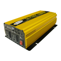
3.2 GP-SW1000
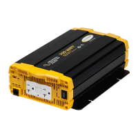
3.2.1 Front view (GP-SW1000)
a) On / Off switch
c) Input level
d) Load level
e) Status
f) Ventilation ports h) Power saveg) Frequency
b) AC outlets
a. ON / OFF switch:
Power ON/OFF switch, leave in the OFF position during installation. Leave in REMOTE
position when using optional remote.
b. AC Outlet: Ground Fault Protected (GFCI)
Outlet sockets available: North America
c. Input Level:
Displays input voltage. Green indicates normal battery level, yellow indicates mid to low
battery level and red indicates under voltage.
d. Load Level:
Displays AC load watts. Green indicates normal operation; yellow indicates mid to high
operation and red indicates overload levels.
e. Status Level:
Displays operating condition. Green indicates normal, flashing green indicates Power
Saving mode, and red indicates a Fault. See Section 5 for Power Saving and LED
variations in Fault mode
f. Ventilation Ports:
Do not obstruct, allow at least one inch for airflow
g. Frequency:
Typical North American setting is 60 Hz. Set dip switch S4 to “0” for 50Hz and “1” for
60 Hz
h. Power Save:
Puts inverter to sleep until a load is present

 Loading...