26 27
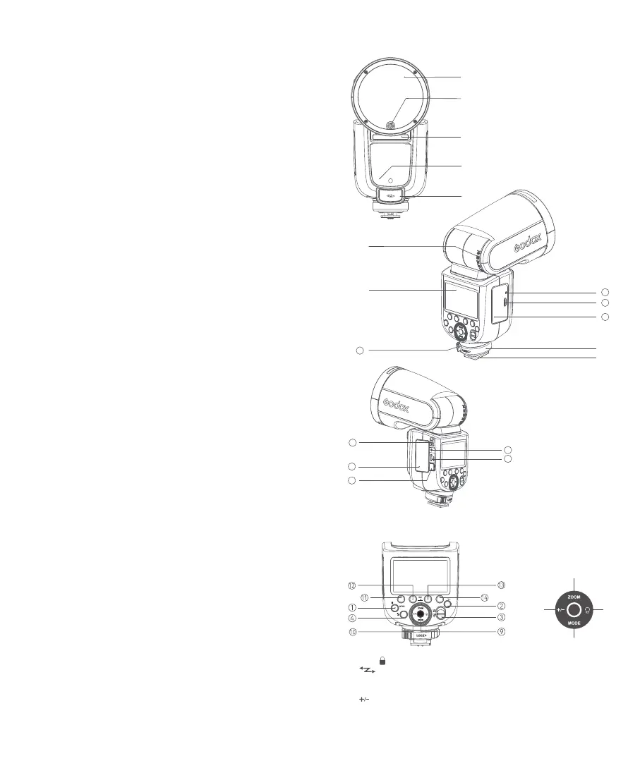
Name of Parts
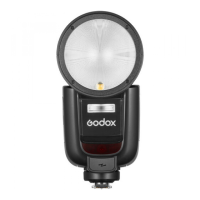
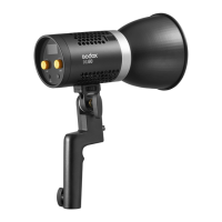
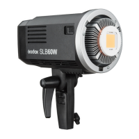
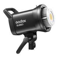
Body
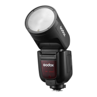
Control Panel
1. MENU/< > Button
2. <
> Wireless Button
3. ON/OFF Power Switch
4. Test Button / Recycle Indicator
5. <
>FEC/Flash Output Setting Button
6. <ZOOM> Zoom Button
7. <MODE> Mode Button
8. LED Modeling Lamp Button
9. Set Button
10. Select Dial
11. Function Button 1
12. Function Button 2
13. Function Button 3
14. Function Button 4
1. Flash Head
2. LED Modeling Lamp
3. Optical Sensor
4. External Flash Interface
5. External Power Pack Port
6. Bounce Angle Scale
7. Hot Shoe
8. LCD Panel
9. Hot Shoe Fixing Buckle
10. Lithium Battery
11. Hot Shoe Lock Ring
12. USB-C Charging Portt
13. Charging Indicator
14. TTL/M Mode Toggle Switch
15. Battery Compartment
16. Battery Remove Button
17. Sync Cord Jack
18. USB-C Upgrading Port
Contents
Foreword
Main Features
Name of Parts
Body
Control Panel
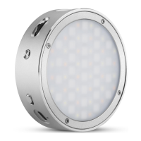
Detachable Sub Flash SU-1
LCD Panel
What's Inside
Separately Sold Accessories
Battery
Battery Level Indication
Power Management
Modeling Lamp
Mounting/Detaching the Camera Flash
Installing/Detaching SU-1
Using SU-1
Flash Mode — TTL: Auto Flash
FEC (Flash Exposure Compensation)
High-Speed Sync
Second-Curtain Sync
Flash Mode — M: Manual Flash
Flash Mode — Multi: Stroboscopic Flash
Wireless Flash Shooting: 2.4G Wireless Transmission
Wireless Settings
Setting the Transmitter Unit Flash Mode
Wireless Channel Settings
ID Settings
Scan the Spare Channel
TTL: Fully Automatic Wireless Flash Shooting
M: Wireless Flash Shooting with Manual Flash
Multi: Wireless Flash Shooting with Manual Flash
TTL/M Mode Switch Function
Screen Lock
Mode Lock
The Reason & Solution of Not Triggering in Godox
2.4G Wireless
Other Applications
Sync Triggering
Bounce Flash
ZOOM: Setting the Flash Coverage
Low Battery Warning
C.Fn: Setting Custom Functions
Protection Function
Technical Data
Troubleshooting
Firmware Upgrade
Compatible Camera Models
Maintenance
25
25
27
29
29
30
30
30
30
31
31
31
32
33
34
35
42
42
44
44
46
47
47
47
48
⑥
⑤ ⑧
⑦
①
②
④
③
⑤
15
17
18
16
⑧
⑦
⑨
11
10
12
13
⑥
14
 Loading...