MODE
ZOOM
SYNC
SLA
VE
SET
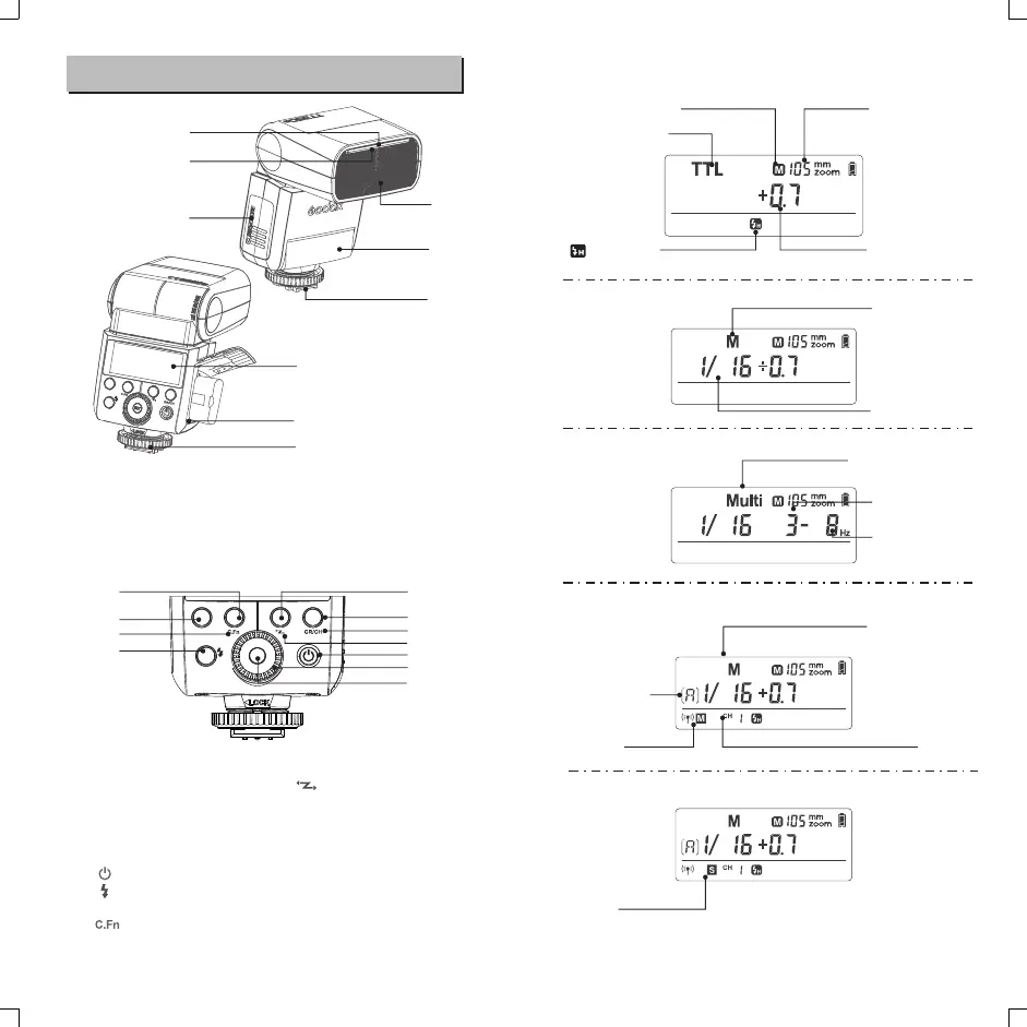
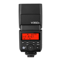
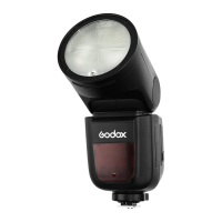
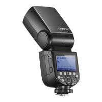
01. Catchlight Panel
02. Built-in Wide Panel
03. Flash Head
04. Optic Control Sensor
05. Hotshoe
06. LCD Panel
07. Lock Ring
08. Battery Compartment
09. USB Port
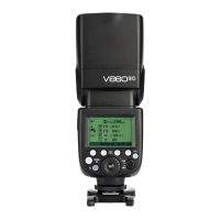
● Body
10. <MODE>Mode Selection Button
11. <ZOOM>Zoom Selection Button
12.<SYNC>High-Speed Sync Button
13. <SLAVE> S1/S2 Optic Slave
Triggering Selection Button
(in non-wireless mode)
14. < > Power Switch
15. < > Test Button / Flash Ready
Indicator.
16. < >Custom Function Setting
Button (reusable button, long
press for 2 seconds)
17. < > Wireless Selection
Button (reusable button, long
press for 2 seconds)
18. <GR/CH> Group/Channel Button
(reusable button, in wireless
mode)
19. Select Dial
20.<SET> Set Button
● Control Panel
● LCD Panel
Name of Parts
(1) TTL Autoflash
: High-speed
sync (Page 36)
02
01
03
04
05
08
11
12
10
15
20
19
14
13
16
17
18
Zoom : zoom display
TTL : TTL autoflash
Focus length
Flash exposure
compensation amount
(2)M Manual Flash
M : Manual flash
Manual flash output
(3)Multi Flash
Multi : Stroboscopic flash
Number of flashes
Flash frequency
Flash mode
Channel
(4) Radio Transmission Shooting
● Master Unit
Firing group
● Slave Unit
Master
Slave
06
07
09
- 31 -
- 32 -