40
41
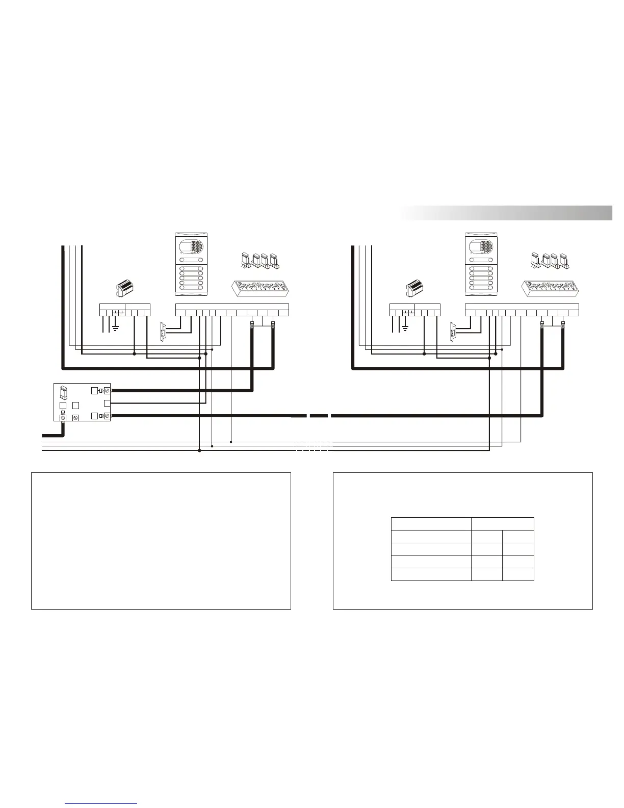
INSTALLATION DIAGRAMS
1,50mm² 2,50mm²
0,25mm² 0,25mm²
RG-59 RG-59
Terminal
SECTIONS CHART
100m.
Distance
300m.
A , A , A, D
in out
V , V , V , V
in+ out+ in out
+, –, CV+, CV–
E S
+
S1
S2
SEC
PRI
~~
+ +
--
CV+CV- D
Malla
Vin-AinAout Vin+ Vout-Vout++
CN1
-
SW1
SEC
PRI
~~
+ +
--
CV+CV- D
Malla
Vin-AinAout Vin+ Vout-Vout++
CN1
-
SW1
JP
4321
JP
4321
D4L-PLUS
JP1
FA-Plus/C or FA-Plus
BUILDING 127 BUILDING 128
Main
FA-Plus/C or FA-Plus
Main
To the monitors To the monitors
IMPORTANT NOTES:
To wire and configure the system properly, use this instruction manual and the ones enclosed
in the internal building door panels.
The installation diagram shows the connection of a video system with two general entrance
door panels and up to 128 internal building door panels.
In case of more than two general entrance door panels, wire them as the second is connected.
In video systems, use a D4L-Plus distributor at each door panel input except on the last one.
Remove the end of line jumper of all the distributors except in the last one.
In case of audio systems only, do not use coaxial cable neither distributors. On the buildings
backbones coaxial cable must be replace by a negative wire.
Refer to the previous installation diagrams for monitors or telephones connection.
ideo installation with general entrance door panel
for residential complexes.
v
Coming
from previous page
ideo installation with general entrance door panel
for residential complexes.
v
For longer distances than the specified contact with your distributor.