WIRING DIAGRAMS:
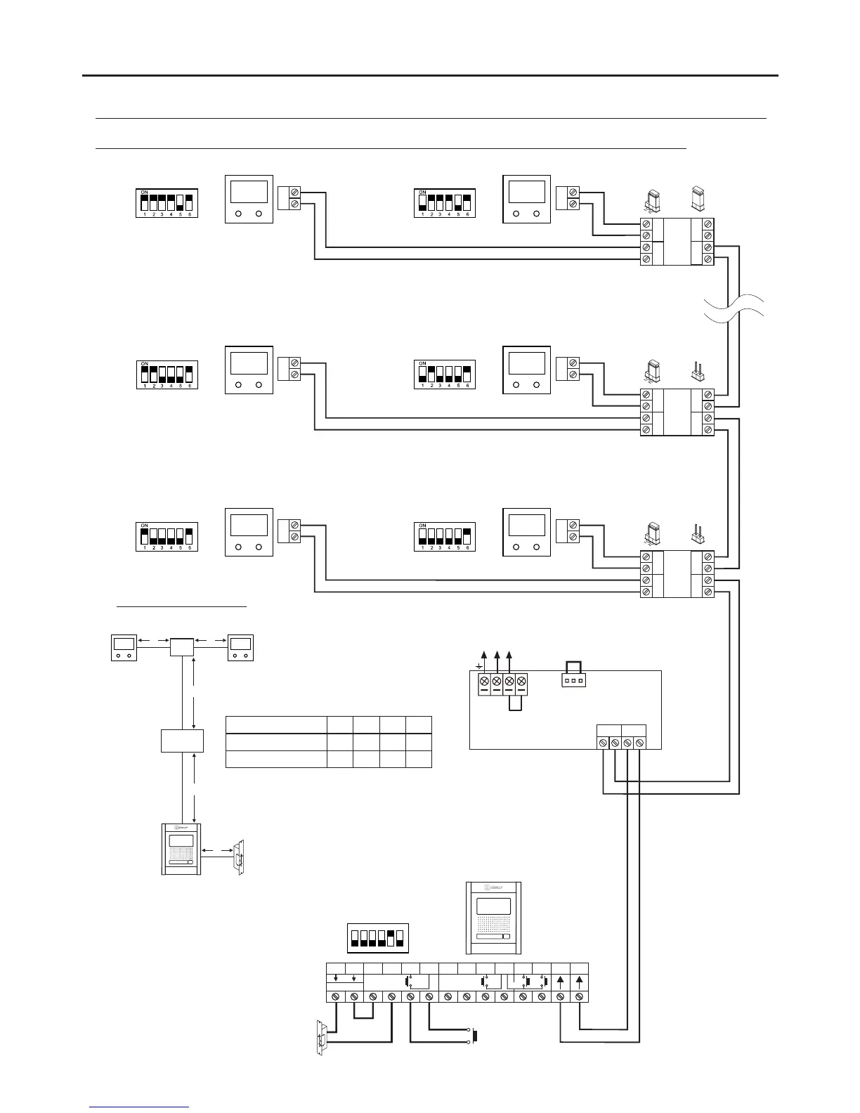
One apartment with 16 VESTA2 monitors, 8 D2L-GB2 distributors and Golmar DC lock release.
15
Configuring the end of line
in the last monitor.
Dip 6 to On.
**
NA2
+
AP-
C1
NA1
AP+
C2
AP+ AP-
P1 P2
BUSBUS
Relay 2
Relay 1
_
12Vdc
Lock release
max. 12 Vdc/270mA.
BUS
BUS
BUS BUS
D2
D1
D2L- 2GB
ON
1 2 3 4 5 6
BUS
BUS
BUS
BUS
BUS BUS
D2
D1
D2L-GB2
BUS
BUS
End of line
ON
CODE 3 CODE 2
** **
Remove the jumper from all
of the distributors except
the last.
*
*
AP
SW1
BUS
BUS
BUS BUS
D2
D1
D2L- 2GB
BUS
BUS
CODE 1 CODE 0
** **
Do not change the factory
default position of the
configuration jumper.
(1)
OFF
(1)
End of line
OFF
End of line
(1)
(1)
Distances and Sections:
D2L- 2GB
A
C
B
C
(2)
(2)
Twisted pair 2x0.75mm
2
Twisted pair 2x1mm
2
60m
A
60m
B
30m
C
80m 80m 40m
Cable
10m
D
15m
D
Important: For AC lock releases or a second lock release, see diagram “Connection of Golmar AC and DC lock releases” on page 19.
( )2
CODE 15 CODE 14
** **
Access paneldoor
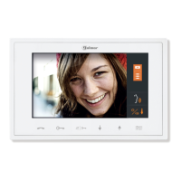
VESTA2VESTA2
VESTA2VESTA2
VESTA2VESTA2
VESTA2VESTA2
FA- 2GB /A
Mains
100~240Vac
N L
CN
BUS (M) BUS(PL)
FA- 2GB /A
L
NEXA MODULAR GB2 VIDEO DOOR ENTRY SYSTEM KIT - VILLAS
 Loading...