WIRING DIAGRAMS:
18
BUSBUS
BUS BUS
D C B A
DP- 2GB A
End of line
OFF
AP AP
Access paneldoor 2
ON
1 2 3 4 5 6
SW1
Access paneldoor 1
ON
1 2 3 4 5 6
SW1
AP AP
Access paneldoor 3
ON
1 2 3 4 5 6
SW1
Access paneldoor 4
ON
1 2 3 4 5 6
SW1
(1) (1)
(1) (1)
Lock release
max. 12 Vdc/270mA.
Lock release
max. 12 Vdc/270mA.
Lock release
max. 12 Vdc/270mA.
Lock release
max. 12 Vdc/270mA.
NA2
+
AP-
C1
NA1
AP+
C2
AP+ AP-
P1 P2
BUSBUS
Relay 2
Relay 1
_
12Vdc
NA2
+
AP-
C1
NA1
AP+
C2
AP+ AP-
P1 P2
BUSBUS
Relay 2
Relay 1
_
12Vdc
NA2
+
AP-
C1
NA1
AP+
C2
AP+ AP-
P1 P2
BUSBUS
Relay 2
Relay 1
_
12Vdc
NA2
+
AP-
C1
NA1
AP+
C2
AP+ AP-
P1 P2
BUSBUS
Relay 2
Relay 1
_
12Vdc
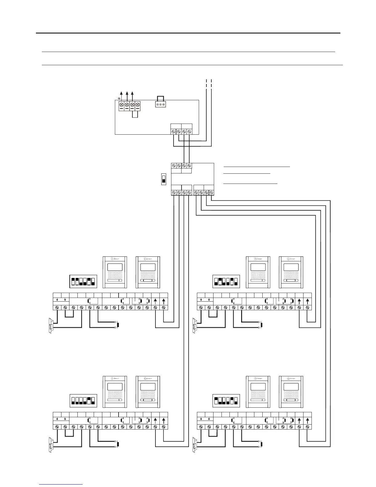
Important: For AC lock releases or a second lock release, see diagram “Connection of Golmar AC and DC lock releases” on page 19.
(1)
(1)
(1)
(1)
(1)
Video door entry system with 4 access panels, DP- distributor for door panels and Golmar DC lock release.GB2A
or or
or or
Mains
100~240Vac
N L
CN
BUS (M) BUS(PL)
FA- 2GB /A
L
NEXA MODULAR GB2 VIDEO DOOR ENTRY SYSTEM KIT - VILLAS
Villa with distributors
Villa without distributors (up to 4 monitors)
Villa with distributors:
Placed to OFF the end of line.
(up to 4 monitors):Villa without distributors
Set to ON the end of line.
( )
*
Important: (in this distributor).
( )
*
 Loading...