39
POWER SUPPLY INSTALLATION
LOCK RELEASE INSTALLATION
ock release installation.
L
If the lock release will be installed in a metal door,
use a Ø3,5mm. drill and tap the hole
In case of wood door, use a Ø3mm. drill
.
.
IMPORTANT:
The lock release must be 12V direct current (cod. 20600149), see page .45
Optionally lock release 12Vac with TF104 transformer and SAR-12/24 relay (see page 46).
etail of the FA-122 power supply installation and technical features.
D
DIN 46277
This device has been exclusively designed to be used on Golmar Kit video .
Golmar will not be responsible of the possible damages caused for an improper use or when used
for other purposes than the specified. Install the power supply according to your country rules.
SV-1370 SII Colour
Input
Power
Output
Working temperature
Dimensions
Weight
230 Vac / 50 Hz
25 VA
17 Vdc 1,5A
0ºC ~ + 35ºC
54(W) x 83(H) x 58(D) mm.
130 gr.
Technical features
IMPORTANT: Replace the protection cover once the input terminals have been wired.
To install the power supply directly on the wall, drill two
holes of Ø6mm. and insert the wallplugs Fix the
transformer with the specified screws
.
.
The power supply can be installed on a DIN 46277
guide simply pressing it To disassemble the power
supply from the DIN guide, use a plain screwdriver
to lever the flange as shown on the picture
.
.
The FA-22 power supply uses 3 units over DIN guide.
The power supply must be installed in a dry and
protected place It's recommended to protect
the power supply by using a thermo-magnetic
circuit breaker and to use a ground connection
.
.
40
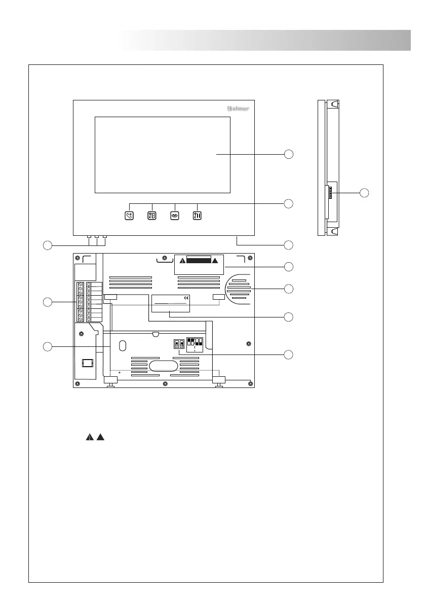
MONITOR DESCRIPTION
escription 1370 SII Color monitor.
D
a.
b.
c.
d.
e.
f .
g.
h.
i .
j .
k
Colour screen 7".
function push buttons.
Menu push buttons (brightness, contrast and colour).
Microphone.
Caution label.
Speaker.
Identification label.
Configuration switches (master or slave).
Call reception volume control.
Attachment holes for bracket installation.
Installation terminals:
3 : Intercom.
2 : Intercom.
1 : Intercom.
, : Ground, Positive.
P2 : Connection to door panel 2.
P2 : Connection to door panel 2.
P1 : Connection to door panel 1.
P1 : Connection to door panel 1.
_
+
_
+
_
+
M 4 x 8
3,5 x 25
DIN-7972
DIN-963
3,5 x 25
DIN-7971
3,5 x 25
DIN-7971
!
.i
3
2
1
P2-
P2+
P1+
P1-
M S
h
f
k
j
-
+
1370 SII COLOR 7"
Nº serie 1304010000
g
C A U T I O N
RISK OF ELECTRIC SHOCK
DO NOT OPEN
!
DO NOT OPEN, RISK OF ELECTRIC SHOCK
INSTALL AWAY FROM MOISTURE OR HIGH TEMPERATURE
INSTALL IN A WELL VENTILATED AREA
b
a
c
d
e
 Loading...